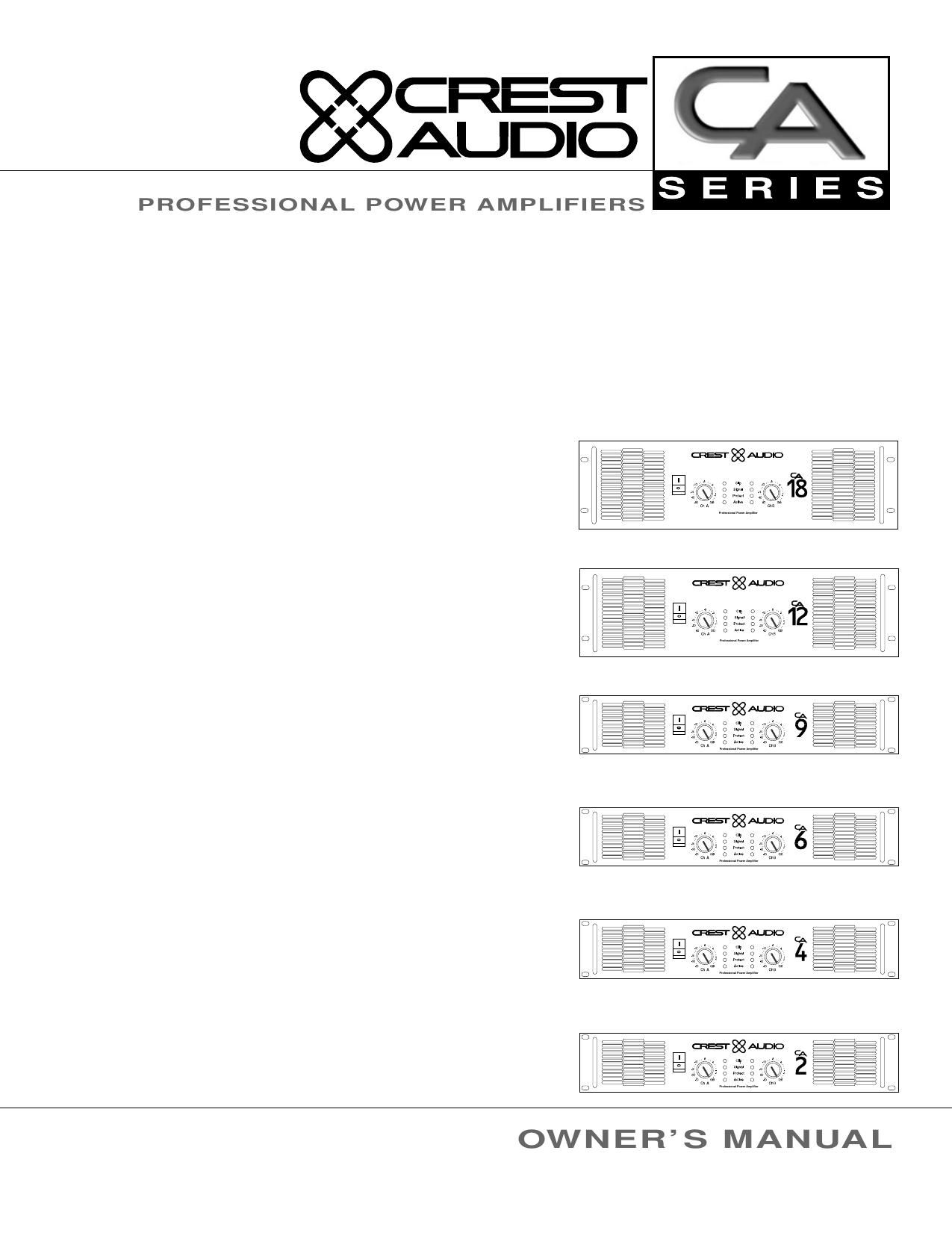
Crest Audio CA 2 Owners Manual

This is the 24 pages manual for Crest Audio CA 2 Owners Manual.
Read or download the pdf for free. If you want to contribute, please mail your pdfs to info@audioservicemanuals.com.

Page: 1 / 24
left right
Crest Audio CA 2 Owners Manual

Extracted text from Crest Audio CA 2 Owners Manual (Ocr-read)


Page 1

CRESI'
AUDIO

PROFESSIONAL POWER AMPLIFIERS

OWNERS MANUAL

Page 2

Important Precautions

This symbol is used to aien the operr
ator to toilow important operating
procedures and precautions detailed
in documentation.

This symbol is used to warn operar
tors that uninsulated dangerous voitr
ages" are present within the equip
ment enclosure that may pose a risk

of electric shock.

. Save the carton and packing material

even if the equipment has arrived in
good condition. Should you ever need
to ship the unit, use only the original
factory packing.

Read all documentation before oper-
ating your equipment. Retain all doc-
umentation for future reference.

. Follow all instructions printed on unit

chassis for proper operation.

Do not spill water or other liquids
into or on the unit, or operate the unit
while standing in liquid.

Make sure power outlets conform to
the power requirements listed on the
back of the unit.

Do not use the unit if the electrical
power cord is frayed or broken. The
power supply cords should be routed so
that they are not likely to be walked on
or pinched by items placed upon or
against them, paying particular atten-
tion to cords and plugs, convenience
receptacles, and the point where they
exit from the appliance.

Always operate the unit with the AC
ground wire connected to the electri-
cal system ground. Precautions should
be taken so that the means of ground-
ing of a piece of equipment is not
defeated.

Mains voltage must be correct and
the same as that printed on the rear
of the unit. Damage caused by connec-
tion to improper AC voltage is not cov-
ered by any warranty.

Have gain controls on amplifiers
turned down during power-up to pre-
vent speaker damage if there are high
signal levels at the inputs.

10. Power down 8; disconnect units from
mains voltage before making connec-
tions.

11. Never hold a power switch in the
ON position if it wont stay there
itself!

12. Do not use the unit near stoves, heat
registers, radiators, or other heat
producing devices.

13. Do not block fan intake or exhaust
ports. Do not operate equipment on a
surface or in an environment which
may impede the normal flow of air
around the unit, such as a bed, rug,
weathersheet, carpet, or completely
enclosed rack. If the unit is used in an
extremely dusty or smoky environ-
ment, the unit should be periodically
blown free of foreign matter.

14. Do not remove the cover. Removing
the cover will expose you to potentially
dangerous voltages. There are no user
serviceable parts inside.

15. Connecting amplifier outputs to
oscilloscopes or other test equipment
while the amplifier is in bridged mode
may damage both the amplifier and test
equipment!

16. Do not drive the inputs with a signal
level greater than that required to
drive equipment to full output.

17. Do not connect the inputs / outputs
of amplifiers or consoles to any other
voltage source, such as a battery,
mains source, or power supply, regard-
less of whether the amplifier or console
is turned on or off.

18. Do not run the output of any amplifi-
er channel back into another chan-
nels input. Do not parallel- or
series-connect an amplifier output
with any other amplifier output.
Crest Audio is not responsible for dam-
age to loudspeakers for any reason.

19. Do not ground any red (hot) ter-
minal. Never connect a hot (red)
output to ground or to another hot
(red) output!

20. Non-use periods. The power cord of
equipment should be unplugged from
the outlet when left unused for a long
period of time.

21. Service Information E q u i p m e n t
should be serviced by qualified service
personnel when:

A. The power supply cord or the plug
has been damaged;

B. Objects have fallen, or liquid has
been spilled into the equipment;

C. The equipment has been exposed to
rain;

D. The equipment does not appear to
operate normally, or exhibits a
marked change in performance;

E. The equipment has been dropped,
or the enclosure damaged.

22. To obtain service, contact your nearest
Crest Audio Service Center,
Distributor, Dealer, or Crest Audio at
201.909.8700 (USA).

Page 6

CRESI'
AUDIO

SERIES

Front Panel

:F C: :> C
<:> :>(:)<:>
<:> <:> :>

: : CRE'Sl' Dlo (:><:><:)
<:>::::)<:> l 5 5 <:><:)<:<:>
<:><:: .0 v a. Clip 0 a <:><:>(:)

:3: o ,- z . <:><:)<:>
<:>(:><:) .5 7-6) Slanal 5 <:>(:><:)
(:> <:) l 2:):
<:><:)<:)<:> 3° , c 0 PM 3° , : <:><:><:>
<:>(:><:> v30 ma 0 Active no ads <:>(:><:>
<:><:)<:> ChA cm :><:>(:)

Q mam... Power Ampliller C)

1. Rack Mounting Ears. Never try to hold the
Two front panel mounting holes are provided on each mounting ear. circuit breaker/power
switch in the ON

position if it wont stay
there itself!

2. Optional Rack Handles.

Available from your authorized Crest Audio supplier.

3. Fan Outlet Grills.

CA Series amplifiers are cooled by two, rear-mounted fans. Cool air flows over the heat sinks and exhausts
through the front grills. Make sure these outlets remain clear to allow unrestricted air flow.

4. AC Power Switch/Circuit Breaker.

CA Series amplifiers have a front-panel combination AC switch and circuit breaker. (No fuses are used.) If
the switch shuts off during normal use, push it back to the ON position once. If it will not stay on, the
amplifier needs servicing.

5. Signal LED.

Illuminates to indicate that a signal (above a minimum threshold) is present at the amplifier input, and that
the signal is being amplified.

6. Clip LED.

Illuminates at the clipping threshold. Continuous illumination also indicates that ACL (Active Clip
Limiting) protection circuitry is engaged.

7. Active LED.

Indicates that AC power is connected and the amplifier is turned on.

8. Protect LED.

Indicates that the channel is in Protect mode (speakers disconnected by output relay).

9. Input Attenuators.

Two input attenuators adjust level for their respective amplifier channels. In Bridged Mono Mode, both
attenuators are used to control signal level and must be adjusted to the same setting.

Page 6 Crest Audio CA Series Power Amplifiers
Models CA2, CA4, CA6, CA9, CA12, CA18

Page 19

CRESI'

AUDIO Appendix B - CA Block Diagram
S E R I E S
R
v-
T CHANNELA
PREAMP
2 + NON-INVERTED
' ATTENUATOR
OUTPUT STAGE
3 2/3 T 17
' - INVERTED f
1 PIN 2/ 3 + A A g F
JUMPER _ +
(REAR PANEL SWiTCH OUTPUT RELAY
ON cm) AMP FRONT END
1 PREAMP INCORPORATES INPUT
BRIDGED SENSITIVITY/VOLTAGE GAIN JUMPER
- (REAR PANEL SWiTCH ON CAIS)
PARALLEL
- +
_ ATTENUATOR UTPUT TA E
R STEREO _ i O s G 17
v- SWITCH f
T PREAMP g f
CHANNEL B AMP FRONT END OUTPUT RELAY
B NON-INVERTED
2 +
3 2/3
' B
1 _ INVERTED
PIN 2/3 +
JUMPER
(REAR PANEL SWiTCH
ON CAVE)
Crest Audio CA Series Power Amplifiers Appendix B

Models CA2, CA4, CA6, CA9, CA12, CA18

Page 23

CRESI' Appendix E
AUDIO CA18 Power Amplifier - Special Functions

SERIES

The CA18 rear panel features external switches for the following:

XLR Pin+ Switch: This switch configures XLR input connection polarity. Either pin 2 or pin 3 may be
selected as the hot" (+) pin. Amplifiers are shipped pin 2 hot (+) from the factory.

Gain Switch: This switch permits the amplifier to be configured for the standard input sensitivity (.775V
for rated power @ 89), or for optional voltage gains of X40 or X20. Refer to the specifications for input
sensitivity values at optional voltage gains of X40 and X20.

NOTE: on the 5-way Output Binding Post version of the CA18, two pairs of5-way binding posts are provid-
ed for each channel, so that paralleling ofspeakers is possible.

ALWAYS power down the amplifier before changing settings
with either the XLFt Pin+ switch or the Gain switch!

CA18 Binding Post Version - Rear View

XLR Pin (+) Switch Gain Switch

CA18 Speakon Version - Rear View

Crest Audio CA Series Power Amplifiers Appendix E
Models CA2, CA4, CA6, CA9, CA12, CA18