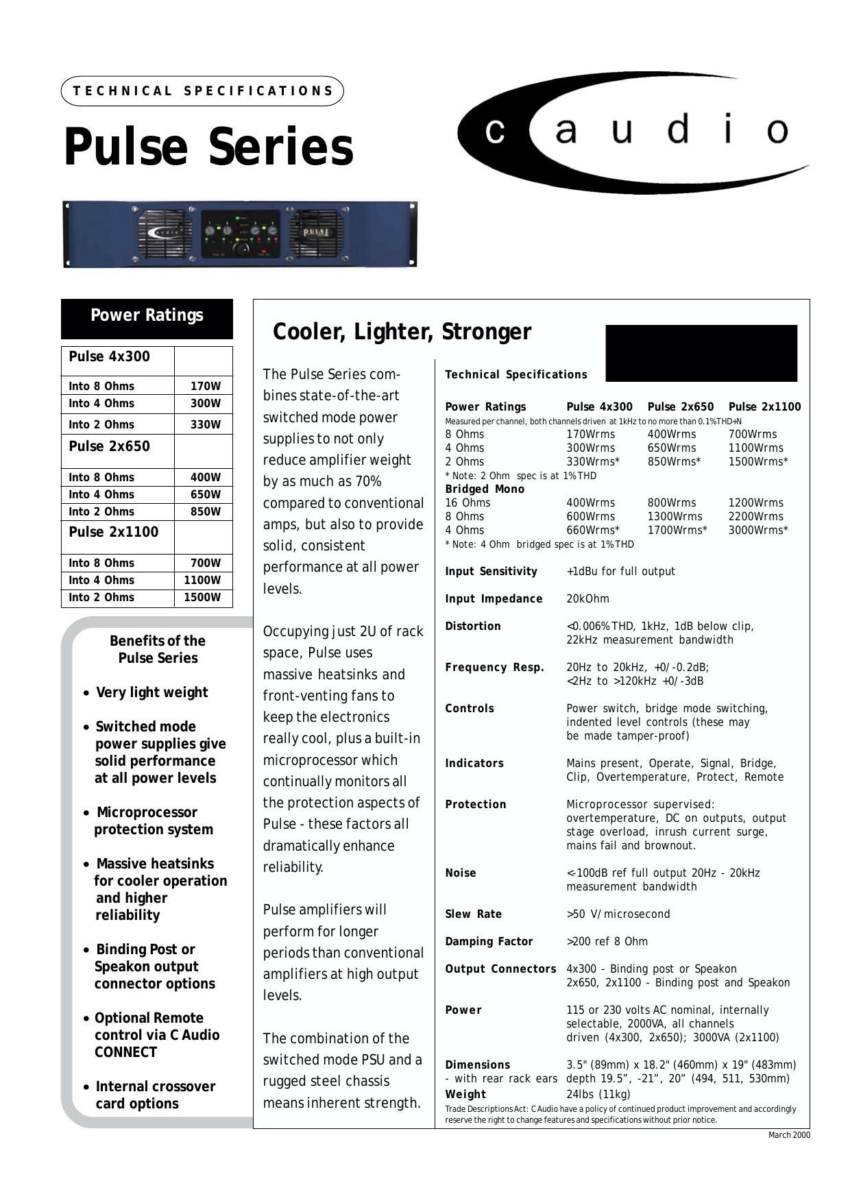
Crest Audio A Pulse Series Catalog

This is the 35 pages manual for Crest Audio A Pulse Series Catalog.
Read or download the pdf for free. If you want to contribute, please mail your pdfs to info@audioservicemanuals.com.

Page: 1 / 35
left right
Crest Audio A Pulse Series Catalog

Extracted text from Crest Audio A Pulse Series Catalog (Ocr-read)


Page 1

Pulse P2X1100 circuit description 1.switching power supply 2.power amplifiers 3.protection 4.frontpanel & flashing lights 5.PIC and system protection

Page 2

1. Switching Power Supply Mains voltage is inserted via filtered IEC CN3. Earth is connected directly to chassis from the body of CN3. Live passes through fuse F2. Live and Neutral pass though a further filter consisting of C2 (X2 rated), L1 - a common mode choke - and C15 & 14 (Y2 rated). Live passes through the soft-start system, TH1, R14 and RLY1. R14 limits the initial current surge caused by the primary reservoir capacitors charging up. TH1 protects R14 if a fault causes excessive dissipation in R14. RLY1 shorts out TH1 and R14 when the PSU is running. Live and Neutral then pass to bridge rectifier BR2 which, for the 230V setting full-wave rectifies mains, smoothing performed by reservoir capacitors C22,23,44,45,32,33. In the 115V setting, this power supply is configured as a voltage doubler. Thus, the High Tension (+HT) DC generated is approximately equal for 230V mains and 115V mains. This will result in about 320Vdc between LIVE GND and +HT. LIVE GND is named as such because it is not isolated from mains but it is the reference point for the PSU. If you need to stick a scope probe around the primary side with the unit plugged in you must connect mains via an Isolation Transformer. Without this, at best you will only trip your RCD breaker, at worst you or your scope may not live to regret it. Do not forget that 320Vdc is still pretty shocking whether it is isolated or not. R36 and R37 ensure proper voltage sharing of the reservoir capacitors. Power for the switching controller circuit is provided from two sources. At start-up, the power comes from R93,113, ZD2, D22 and C75. C75 is charged up to about 47V through D22 from Zener regulator R93,113 and ZD2. The command to start the PSU comes from the PIC (+5V for off, 0V to switch on) via R33. The LED in OPT1 is turned on which turns the transistor on, shorting out pins 5&4. While the transformer windings are cooler than 120 0C the thermal cut-out (TX5-B) will be a short circuit. So R166 will be connected to the top of C75 and will form a Zener regulator with ZD9. The output of this zener regulator is buffered by TR49 which then powers the switching controller circuit. C75 stores enough energy to run the controller for long enough until the second source of power is ready. The second source of power comes from the transformer on pins 3 and 14. This secondary is voltage doubled by C82, D29,31 and C74 and produces about 48Vdc on VAUX. This is connected via D32 to the top of C75 so the controller circuit can continue running. VAUX is used to directly power RLY1 to short TH1 and R14 out while the PSU is running. The circuit comprising R165,R172,ZD10,R178,TR47 and R180 shut down the PSU when the voltage on C75 falls below about 32V. while the voltage on C75 is greater than 32V, TR47 is switched on and pulls pin10 of IC6 down to 0V which enables IC6. When the voltage on C75 falls below 32V, TR47 switches off and pin10 of IC6 is pulled up to 20V through R180, disabling IC6. R92,8,85,C67,ZD3 and TR23 form a time delayed drive for RYL2. At start-up, RLY2 will be open and R127,145 will be in series with the primary of the transformer. These resistors limit the current surge caused by charging up the secondary reservoir capacitors C113,114,137,138. About 100ms after a successful start-up, TR23 will energise RLY2, shorting R127,145. The switching controller circuit is based around IC6, and SG3525 PWM controller. Switching frequency is set by R175 and C199 to about 85kHz. R176 controls the dead time period, setting it to between 500ns and 1µs. Outputs appear at pins11 and 14. These two outputs are complementary, that is when one is high (20V), the other is low (0V). Due to the dead time control, neither outputs are high at the same time but both are low for the dead time period. These outputs are fed through R169,170 to high current buffers TR40,41 and TR42,43. The buffered outputs push-pull drive the primary of Pulse transformer TX4. R160 is a damping resistor used to minimise ringing caused by imperfections in TX4. The transformer has two secondaries, each driving one IGBT in anti-phase. The turns ratio is 1.5:1 (pri:sec) and due to the push-pull connection of the primary, the output of TX4 swings positive to about 15V to turn

Page 5

appear across R100 and R146 whilst double the normal voltage will appear across R99 and R137. Should this not be the case, it indicates a fault in the input stage itself. The same process should now cause TR37 and TR20 &21 to be off and TR81 to be full on-¦

Page 30