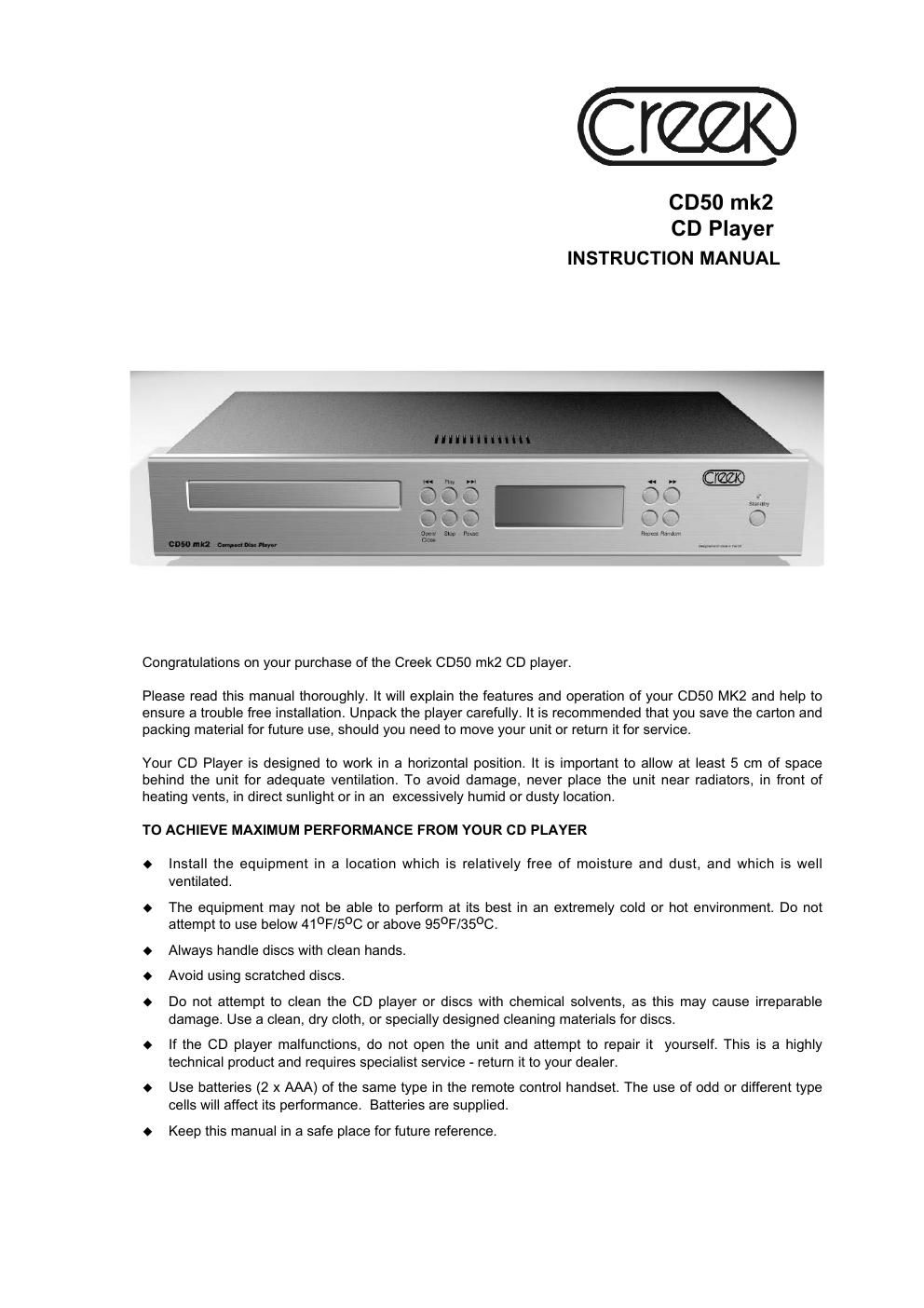
Creek cd 50 mk2 owners manual

This is the 12 pages manual for creek cd 50 mk2 owners manual.
Read or download the pdf for free. If you want to contribute, please mail your pdfs to info@audioservicemanuals.com.

Page: 1 / 12
left right
creek cd 50 mk2 owners manual

Extracted text from creek cd 50 mk2 owners manual (Ocr-read)


Page 1

2 SAFETY INFORMATION Designed to operate on 220-240 Volts 50Hz AC or 110-120 Volts 60 Hz AC, the CD50 mk2 is supplied with a mains lead with a fitted 3 pin plug suitable for the country of use. Should this plug need to be changed please note that the wires in the mains lead are coloured in accordance with the following code: Blue-Neutral Brown-Live Green/Yellow-Earth CONNECTING THE COMPACT DISC PLAYER -¹ Before connecting or disconnecting a unit from your audio system, make sure that you switch off the power to each component. -¹ Ensure that you make the correct connections, paying attention to the L (left channel) and R (right channel) marks. Plug in the cable securely. Loose connections will result in unsatisfactory sound reproduction or noise problems. -¹ If this unit interferes with the tuner, switch it off during tuner operation. REAR PANEL Line Out sockets Connect one end of the interconnect cable to the unit's AUDIO OUTPUT sockets and the other end to the sockets labelled CD or AUX, or to other line inputs on the amplifier. Do not connect it to the amplifier's PHONO input if a phono circuit is installed, as it is meant for vinyl disc, not compact disc. Digital output This output enables you to connect the CD player to a stand-alone D to A converter in order to convert the digital signal to analogue. The digital output can be accessed via the co-axial or optical TOSLINK S/PDIF socket on the rear panel. Ask your dealer for details of interconnects if required. Controls 1 & 2 Control port 1 & 2 are expansion sockets for an optional isolated serial control interface. To use this requires a dealer upgrade. AC Power socket IEC type 220V-240 V AC or 110V-120 V AC AC Power Cord After completing the installation and all connections, make sure that the POWER switch on the back panel of the unit is set to off (O). Then plug the power cord into a live AC outlet. NOTE The equipment has been tested and found to comply with the limits for a Class B digital device, pursuant to Part 15 of the FCC Rules. These limits are designed to provide reasonable protection against harmful interference in residential installations. This equipment generates and can radiate radio frequency energy and if not installed and used in accordance with the instructions may cause interference to radio communications. However, there is no guarantee that interference will not occur in some instances. If this product causes interference to radio or television reception, which can be determined by turning the equipment off and on, try to correct this by one or more of the following measures: Reorient or relocate the receiving antenna. Increase the separation between the equipment and the radio or TV receiver. Connect the equipment into a mains outlet on a circuit different from that to which the receiver is connected. Consult the dealer or an experienced radio/TV technician. CD50 mk2 Compact Disc Player

Page 2

3 EXPLANATION OF CONTROLS 1.STANDBY button 7.SKIP BACKbutton 2.Disc Tray 8.SKIP FORWARDbutton 3.OPEN/CLOSEbutton 9.SCAN BACKbutton 4.STOPbutton 10.SCAN FORWARDbutton 5.PAUSEbutton 11.REPEATbutton 6.PLAYbutton 12.SHUFFLEbutton DISPLAY 2 3 4 5 11 12 1 7 6 8 9 10 A.TRACK NUMBER display G.SCAN indicator B. PLAY indicator H.SHUFFLE PLAY indicator C.TOTAL TIME indicator J.A « B PLAY indicator D.REMaining time indicator K.REPEATindicator E.PLAYING TIMEdisplay L.REPEAT 1 indicator F.PROGRAM indicator M.PAUSE indicator A B C D E F G H J K L M CD50 mk2 Compact Disc Player