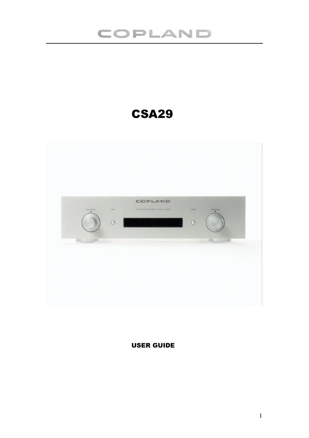
Copland csa 29 owners manual

This is the 5 pages manual for copland csa 29 owners manual.
Read or download the pdf for free. If you want to contribute, please mail your pdfs to info@audioservicemanuals.com.

Page: 1 / 5
left right
copland csa 29 owners manual

Extracted text from copland csa 29 owners manual (Ocr-read)


Page 1

2 Introduction We would like to take this opportunity to thank you for selecting the CSA29 amplifier. We at Copland wish you many enjoyable hours in the company of fine music. Please read this owners manual before operating the equipment. CAUTION ! Various regulation agencies require us to bring the following information to your attention. Please read carefully. WARNING ! To prevent fire or shock hazard, do not expose this unit to rain or moisture. ! Check that your supply voltage is the same as indicated ! Dangerous voltage inside. Do not open the cabinet. There are no user serviceable parts inside. Repairs should be carried out by qualified service personnel only. ! Ensure that no objects or fluids pass through the ventilation openings. If liquid is spilt into the amplifier, disconnect from the mains and consult a qualified service technician. Installation Open the carton and remove the amplifier from its plastic bag. The AC-power cord is placed in the bottom of the carton. Before placing the unit in your home read this carefully. Do not subject the amplifier to high mechanical vibration, the valves are sensitive to this. The trouble free life of an electronic instrument is greatly extended by providing sufficient ventilation to prevent the build up of high internal temperatures that cause deterioration. Allow enough clearance so that cool air can enter at the top. With adequate ventilation the amplifier can be mounted in any position. The recommended minimum space is 45 cm deep, 45 cm wide and 30 cm high. Input / Outputs Use shielded cables to connect the signal source to the amplifier input. To minimise the possibility to hum the shielded cables should run parallel to each other or loosely twisted together. Locate the cables away from speaker leads and AC power cords. Selection of the proper gauge wire to connect the loudspeakers reserves the quality of sound reproduction for which the loudspeakers has been designed. If undersize wire is used, resistance is added to the amplifier/loudspeaker combination, which adversely affects the performance. Added resistance causes reduction of the damping characteristics. All connections is made on the back panel of the amplifier. AC Power The amplifier AC power cord is plugged into a 110/120/220/240 volt 50/60 Hz wall outlet. The right voltage is indicated on the back panel under AC power inlet.

Page 2

3 Front Panel 1 2 3 4 1. Source Selector : Selects the appropriate input signal source. 2. Tape Monitor : If you have connected a tape recorder or a cassette deck to the tape in on the back of the unit, then switching Tape will make it possible to listen to tapes. If your tape recorder has a monitor capability (usually requires a separate playback head), then you can monitor your tape recording as it is being recorded by switching the tape button. NOTE : When the Tape monitor is engaged it bypasses the Selector Switch. Regardless of witch source the selector is set for, you only hear the tape if the Tape Monitor is accidentally left on, none of the inputs on the Source Selector will operate. 3 : Power switch : By pressing this key, the amplifier will switch cyclically between operation and standby mode. Power on or Stand By will be indicated in the display. 4 : Audio Level : To adjust the volume to the desired listening level. Turn the control clockwise to increase the volume.