Classe audio dr 7 owners manual

This is the 5 pages manual for classe audio dr 7 owners manual.
Read or download the pdf for free. If you want to contribute, please mail your pdfs to info@audioservicemanuals.com.

Page: 1 / 5
left right
classe audio dr 7 owners manual

Extracted text from classe audio dr 7 owners manual (Ocr-read)


Page 1

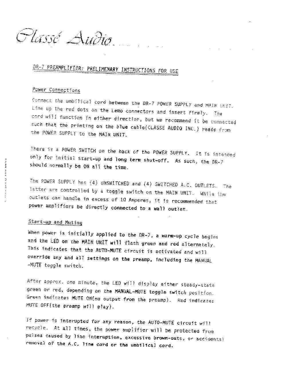
W EKNPLIFEER: PRELIHEHARY INS TRfiCT 095 FOR USE

"a} :grd bfifiween the BER? :9QHE9 SUPPL¥ Aué AKA

cm the Limo connecters and msert firm}: TM
'9 eitfisr directia? 99% we re:


wmfiné ii ée v

tfit printing er the h7ue cahieiCLAESE AUBEG 39%.} reads
9 ' HAIR UNETE

°ha
aflsz

SHITEH Cm the back 0. the PGJER SUPPLL It I .
sLart-up and iong term shut-off. As such; the BA»?

E
y 96 99 532 Aha time.


EML {SYS gen u&33.&

grtun and Eating

anen pawer is initially applied to the DR- 7 a warm-up cycie bagins
anfi the LE9 as the 9A29 33E? ai§3 fiafia green anc red a§ternatezy.
9:15 finsfimtes thfli t3}: AmmmTE cwrcegit is actwatm. and wax;

everriae any and a}? settings on the preamp, fnciud$ng the HANUA
«9335 taggle :fiiich.

:83 fiuTE 39(9n Cutput from t; pream3}. Re
9675 OFF{the araamg w??? g7ay)..

CL 3* N

If pawer is interupted far afiy reason, the AUTD~MUTE circuft H13}
At a}? timasx tfie yowtr AmpEEIier wili be prsiecfea fvum
wvzses caused by 11n$ xnteruption, ex.cessive brown-outs, or ACCS
rafinvai a? the A. C Eina card cr the umb111ca1 card.

Page 2

Phoug_lnguts

Each phone input has comp1ete f}exihiiity for gain, impedance, and
capacitance settings. If your DR~7 contains headvamp beards, you
may safest between MGVING CUIL and MOVING MAGNET gain. The top switch
aé§ng the row af dip switches marked RES. is 1ab971e6 MC Ur HM? far
MGVIMG CQIL or MGVIHG MAGNET gain respectively. The cthér switches
5: that row seiect the phone input impedance.
EMPQRTANT NOTE!: IF YOUR DR-7 SPECIFICéLLY CENTRENS fiILn3
HEAD-Afi? BOARDS, IT HAS NATURAL IMPEDANC LGADEfiE éfifi Afiiflx
MATICALLY SETS THE INPUT IMPEDANCE FGR ANY MOVING COIL CARTRIQGE¢
Do me? USE ANY 9THER SWITCH SETTIMGS IN THIS EASE. T0 00 53
NILL QflLY LGAD DOWN THE CARTRISGE EXCESSIVELY AND DEGRABE THE
SQENQK
is another row of dip switches. These are markeé £A?-, and

" usad to taiisr the high Frequency response of magnetis cari~

3f the abeve aypiies equa3}y to 9HGN9 1 0r fiBORfi 2. The Settiugg fer
each wiTI be retainefi and se1ected by the frnnt pane] seTector switch,

*(ths: Each ?hsna inpat can be set to MC 0r NH, but 36TH phone inputs CéfififiT

.T '3:
H1 h Level qugg; be set to NH h1s HI}? not work ,

fiigh Esve? inpvts &re prcvfded for the fOIIOwing: Auxi11ary {AUX},
Tunsr-TU#ER), iompact Uisc§66i with specfal features(see below),

twc Tape 100ps \TAPE 1, YAPE Z}. Incfiusion of the two Tape inputs
1339 with the MONITOR switches permits cross-dubbing betwegn taye

. . . I

as amayor listening ta a secsnd scarce sfimVEtaneausty.

W

L9
(12

CD In at

A

The LU input has two basic modes cf operation: FILTERED or DIRECT.
Fer narmai use, set the 79ft dip switch(in a row of six Iocated
between the left and right CD inputs) in the down position. The

CD input will functien normaily thraugh the .figh 1evel stage of the
preamp. You may also use the filter dip switches to attenuate the
high frequency response of CDs or CD Piayers. Leave tha first switch

fin the same posit1on(down). but se7ect tha athers<1~5) for an equivalent