Carvin ht 750 owners manual

This is the 2 pages manual for carvin ht 750 owners manual.
Read or download the pdf for free. If you want to contribute, please mail your pdfs to info@audioservicemanuals.com.

Page: 1 / 2
left right
carvin ht 750 owners manual

Extracted text from carvin ht 750 owners manual (Ocr-read)


Page 1

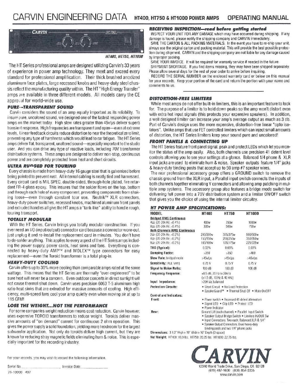
CARVIN ENGINEERING DATA tiraoo. HT750 s HT1000 power: AMPS OPERATING MANUAL

£1759.

NM. [11750. #710110

The HT Series professional amps are designed utilizing Garvin's 33 years
of experience in power amp technology. They meet and exceed every
standard for professional amplification. Their thick brushed anodized
aluminum face plates. large recessed knobs and heavy-duty steel chas-
sis retlect the manufacturing quality within. The HT High Energy Transfer
amps are available in three different models. All models carry the CE
approval for worldwide use.

HIRE-TRANSPARENT SOUND

Carviti considers the sound of an amp equally important as its reliability. To
insure pure. uncolored sound. we designed one of the fastest responding power
amps on the market today. High slew rates greater than 45v/ps deliver superb
transient response. High frequencies are transparent and open-even at extreme
levels, I tnear feedback circuits reduce distortion to near the theoretical zero limit.
preventing any type of harshness which would lead to ear fatigue. The HT Series
amps deliver flat. transparent. unaltered sound-especially important to the studio
user. And you can drive any type of reactive loads. including 70V transformer
distribution systems. These amps are designed to deliver non-stop, continuous
power and are coniplelely protected frotrt heat and short circuits.

ULTRA RUGGED FOR TOURING

Every chassis is tiiade from heavy-duty 16 gauge steel that is galvanized before
being painted to prevent rust. All internal cabling is neatly tied and harnessed.
Every circuit card is MlL SPEC. double-sided. througli~ltole plated. lire retar-
dant FR-4 glass epoxy. This insures that the solder flows on the top. bottom
and through each hole of every component. preventing components frorri stiak<
ing loose-even through constant tour use. Neutrik'M XLR connectors.
heavy-duty power switches. recessed knobs. machined aluminum front panels
and extruded handles all give the HT amps a "tank-like ability to handle tough.
touring transport.

TOTALLY MODULAR

Willi the HT Series. Carvin brings you totally modular construction It you
ever need air I/O (input/output) connector card because a connector wore-out.
just unplug it arid re-install the replacement card in minutes. You don't have
to de-solder anything. This applies to every aspect of the HT Series amps includ-
ing the power supply. power cards. heat sinks arid fans. Everything is con-
nected by heavy-duty AMP'M and MOLEX1M type connectors for easy
replacement-even the Toroid transformer is a total plug-in.
HEAVY-DUTY COOLING

Carvin otters up to 30% more cooling than comparable amps rated at the saute
wattage. This means that the HT Series are thermally overactigitieered to be
sure heat erI never be a concern. Even outdoor concerts in direct sunlight will
not cause thermal strut down. Carvin uses piecisiori 6063 T-5 aluminum high
ratio treat sinks that are extruded for tnassive amounts of cooling. High effi-
ciency. multi-speed tans cool your amp quietly even when moving air at up to
i 15 CFM!

LOSE THE WEIONI'...NOT TNE PERFORMANCE

For some companies weight reduction means cost reduction. Carviti however.
uses expensive TOROID transformers to reduce weight. Toroids deliver mas-
sive amounts of "on demand" current for continuous 2 Ditto operation. This
gives the power supply a solid foundation. yielding more headroom for the largest
suhwooler application. Not only do toroids deliver high current. btit they are
known for reducing stray magnetic lields eliminating truth 8. noise. This is espe»
ciaily important for the recording industry.

for your records you may wrslt to record the loiluwitig information.

Serial No gfl
Te-toooo 497

Invoice Datei

RECEIVING INSPECTION-lead before golfing flannel

lNSPECT YOUR UNIT FOR ANV DAMAGE which may have occurred during shipping. If any
damage is found. please notify the shipping company and CARVIN immediately.

SAVE THE CARTON & ALL PACKING MATERIALS. In the event you have to re»sbip your unit.
always use the original carton and packing material. This will provide the best possible protec-
tion during shipment. CARVIN and the shipping company are not liable for any damage caused
by improper packing.

SAVE VOUR INVOICE. It will be required tor warranty service it needed in the future.

SHIPMENT SHORTAGE. It you find items missing. they may have been shipped separately.
Please allow several days for the rest of your order to arrive before inquiring.

RECORD THE SERIAL NUMBER on the enclosed warranty card or below on this manual
for your records. Keep your portion of the card and return the portion With your name and
comments to us.

DISTORTION-FREE LIMITERS

While most amps do not offer built-in limiters. this is an importantfeature to look
for. The purpose of a limiter Is to hold down peaks so the amp won't distort even
with extra hot input signals (this protects your expensive speakers). to addition.
a well designed limiter can increase your amps average output as much as 3 db.
Part of Garvin's design uses the more expensive. distortion-tree linear opto lso~
Iators. Unlike amps that use FET controlled limiters which can inject small amounts
of distortion. the HT Series Iiniiters keep your sound pure and uncolored!
FRONT PANELS I CONNECTING UP

The HT Series feature front panel signal. peak and protect LEDs which let you mon-
itor the status of the amp easily. Also. botli channels use precision 41 detent level
controls allowing you to see your settings at a glance. Balanced 1/4 phone & XLR
input lacks are used to eliminate hum 8. noise. Speaker outputs feature 1/4 jacks
& heavy~duty binding posts that accept up to 50 amp #7 speaker wires.

The rear prolessiotial accessory group offers a GROUND switch to remove the
chassis ground from the XLR input. a Parallel input switch connects the inputs of
both channels together eliminating Y connectors and allowing amp patching in mul-
tiple amp systems. The accessory group also features a bridge mode switch for
delivering full power into a 70V distribution system and a limiter ON/OFF switch
that gives you the choice of using the internal limiter circuitry.

MT POWER AMP SPECIFICATIONS:

MODEL HMIJIT HT75IT HTlflfll)
Brideetmtftflnmimms

431. IZU-ZOk HZ. <0 4%) 400w 150w lUOOw
rut. rztwtii III. to 4%) allow snow IlltM
Bflmflhiflftlliflmififlflflllmfi

2n rattan Hi. (0 2%) 20mm 375/3r5w sou/snow
in porn». | Ir. - u 2%) ISO/150w 250/250w silo/35w
fist izti 20k 1.40 2%) Itltl/lthw l75ll75w 225/2st
nip (Typical): 0.03% 0.03% oozes

Damplng Factor: ,350 >350 >400

Slaw Hale: bridged mode 245v/ps >45v/us >45v/ris
Sensitivlty: Mu. Vms] U 75 V 0 75 V 0 75 V
Signal to Noise Ratio: l00 dB l03 on meat!

frequency Response: 20.5 dB. 20 Hz to 20kHz
l2l5dB.l0H1& 40 klIz)

>20K 52. balanced

0 Short Circuit - No Load Protection
- Speakchuatd' I thermal SliutrOIl - Mute Orr/OFF

Input Impedance:
Protection Circuits:

CDMIO' and Indicators:

Front: - Power switch - Recessed Iii deriint attenuators
- Signal [EU I Clip LED - Protect LED
t Power indicator

Rear: Ground till (each channel) . Parallel Input Switch

- Speaker Output Bridge Switch - LmutetstN/Odl Sw
. Itipul Connectors Two each. Balanced XLR 8. 1/4"
- Speaker Output Connectors Dual heart/duty
binding posts and two l/A" phone iacks
Dimensions: 3 If? Iiigti x 19 Widex 10' Depth (24503.66)
NelWelghli lllililfl lfiSllliS [750 P025 lbs "000 22 75 lbs

CARVIN

12340 World Trade Drive. San Diego. CA 92128
(619)4374600 {BOD} 854-2235
www.carvincom

Page 2

FRONT 8: REAR PANEL CONTROLS

mm u

to
cm 2

-- HT750 7

mLm w. mm m

.. blotter
0 mm


<9 I é)

FRONT PANEL
r. MOUNTING

Sturdy rrnn mere all-"inunr handles rnalm, lnr may lranspnrtrrrg along wulr lacrlrtalrnu rack nrslallarlnn
the rack rttnrrrtlrrtu lrnles arr- rlesrqned on ISO standard snaarng torn tD-JZ x 5" rrhlltru rrrachrne screws
are nrnrnally used to sr-urre the amp Rear support lnar;l

2. POWER SWITCH

tel I the paler-r amp r:nnnnctrnns and verrly the Ill: Irnn power sutrrrze Irnloro rrrruarnnn the POWER
<.','lrlr h the ','0||tl.',t [[D rrnrrrrslakahly rnrlrcates that all rnrnits are properly powered no Yellow was
drawn so the. operator tvnlllrl we the nllrnr rrrtltnflltrrs hour .1 rlrstarrm

3. CIIANNEL LEVEL CONTROL

It prnrrwnr Ill van rrrrrrrt | FVH .ltltturale rs used to arllnsl the vrrlnrne levels In rlt-hvrtr the amps lull
hut/"l wrtlrnnt rrrlurrnu the lrnadleorn ul Ilrr-r srgrrzll source the level rzrnrlrnls slrnrrhl l r rrnrrerl up anprox~
rrrralely It} I IS nn tlrrI rtrnll

4. CHANNEL SIGNAL INDICATOR
Tlrr' own shill/ll LED rr-unators wrll start to tlash when there i< a mortal pawun rn vrnn sneakers t-3tlrlBM)
has lets you Itrrrr'l ",1er the amp I. nassrnn a signal to your rear sneaker Lorrnerzlurs

5. CHANNEL CLIP INDICATOR

llra rallCIll [ID lrrrtrrnlrns wrll start to llashvrhen eachclranrrel has reached rt: Itraxrrrlrrllmlllptll tlcrxrsrunal
tlastnr-n car ran-l lr_.r I'lt'll bass lrnqlterrries is OK However, Lorrsrstertl llushlrrq roused lrorrr Ingher Irenrrerrcres
may tlatrraO? lrrnlr horrunrzcy rlnyers lexccssrve drstortrnn). This does not cause damage In the amp

6. FRONT COOLING VENTS/FAN

llnnn rarlr nulallatrnn the rear ol the amp must be trrlly exposed In morn terrrnelalllrt an the snr
rnurrrIn-rr an clrrnrlrt out he warmer than 120 or the thermal rrrolerdnrn could active the llllJlECl LEI)
the tram r_r)nllrra want: are run In he ttstrrt led lrrnn erhauslrng the warm an

7. PROTECT LED INDICATOR

the red PROTECT LED provides the operator with rrrlornralnrrr about the status nl the anrnhlrer the
PRDIFCT I I'll can rnrrrn on rnrrlel 3 drlIr-rerrt mrrrlrlrorrs (when tlns happens lrrrtlr channels are Irrrrled
try rtr

ll [lurnro power no. the arnnlrhur stays In a united state Irrr annrnx 3 sec nrnrl rI rlelrrnrurres lhnt
everythrnn is luncrrurrrnu normally (no output shorts or over temp conditions)

2) When the output load draws eycessrve current or a dnect strnrt rs detected caused hy a shorted
{maker male or sneaker tyslerrr Reset .tlrrsvcmrdrtrurtuyturuurg the am]; oh [or two seconds and
than on auarrr Chmk lnr shorted cables and the total speaker system impedance connected to
each channel I? ohms mrnlrrrurn rtrtr ctr or It rrhrrrs BRIDGED)

3) nvnrlroatrnu is usually determined when the amp sinus rn tlre rnutrlle nl a nertrnrnrrncrr .1an the
Pltollélfl Hill is no It llns is the muse learyntLre arrruAmrjar Ltoirouljlrearnp down The
anrpwrll :lrlltmrallrftll, reset will")! I to It rnirnrtes the PROIECI [Ell wrtl turn all anlrrrn warty
(,lrrrr;k trn llrn Irrlltrt'lrllu courtrrrarts a) Ilre rear Intake an rs mfiltIlJNL lrl Intake an rs extremely
warm rt lrrrrn evharrnr v vnrs VBSIlltJJd. or d) Ercestrve sneaker load (try other sneakers rrr thrtrtrve
git-aw: rl you Ira;n more than rnrn ( unnamed In each rzlrartnnl) Again, the rnlrrrrrnurr lnrrrertanre
is 2 ohms pnr m m .r unm enrlrntur

REAR PANEL
3. xur crrnrwver. mews

Trn rrrrrstnrrrtncgrrrrrat:rnrrlrralrnus rrsellr YUI halarlrednrnuls IlllS\"IllIrr'll Immune llrlltlall'Ifllltrw
rrl lurloer ra'rln runs lmnr I'ltll srqnal snunn (nrrver olr) ltur ause this rs a Imlnrn rrrt rrllrrll the darn wrll
Irnlrrlfilrrulwtlranrrsnrnllrnt l nrrnrl |-1tk":rlltntrrltralatnrrt lrnes XLRprrlrnrrtiunralrrrn lnrt I§ltltlltllrll
trnnutthlhnGRtlllllllllFl

rem-imman-
nm uncrow-

\
ll,


{WM

9. CHANNEL 1/ PIIONE JACK INPUT

lhrs stereo phone pack is designed to receive either balanced or unbalanced input srgrrals. Balanced stgi
nals cornrrrg rrrtn this )ack should be wrred wrth the connectors up going to signal I and the connectors
run; to srgrrat , The currrrector's sleeve rs then tied internally to ground through the GROUND LIFT swrlclr

TO. PARALLEL OR "Y INPUTS

The rear PARALLEL swttch allows you to dtlve both channels horn erther rrtput. All srgnals entering any
lrrnut \urtl he available on both channels This ellrrurrales V adapter cables Thrs leature rs used to "darsy
rlrarrr" one place at earrrnrnent to another Just plug Into the unused INPUT (t/4" or tht) and rl wrll
become an orrtrrnt lrrr other equipment,

I I. INPUT GROUND LIFT

Marry tnrres sound systems are connected in such a rrranner to cause a grounded loop with the rrrptrts
that result In arrttlhle lrtrrn llrn rnnnl (1/4 8. XLR) GROUND LIFT switch on the rear panel wrtl help elrrn-
nratn tlrrs nrnlrlr-nr. It not. another way to elrnrrnale ground loops rs tn install a true rnatchrrrg" lrarrs~
lorrner Iretween the annrlitrer rnpul and the signal source

I 2. LIMITERS

Tn anlryate the LIMI lEl'tS. engage the rear Iinriter swrtclr The burltnn lrlgh quality lirnlters are recommended
to hold down [leaks that could cause early (hslorlron. Limiters will help to use the average power so that
you can net more uuluut lrorn each channel. To check the etlecllveness of the llrrriters when the channel
starts to distort (under the amps lull output), engage the lirrrrters and hear the reductron at the, distortion.
It the drslurtrrrn stops, you can turn the channel up tor more powert The lower has: Ireouencics are most
allerted WARNING Do not check In an envrrnrrrrrent where the sound level could damage your ears!

'3. SPEAKER OUTPUTS

lhn standard IM SPEAKER racks are used lot rrrosl anullnations Turn the auto otl betore connecting
your sneakers

l 4. SPEAKER BINDING POSTS

For heavyrduw speakerconnecllons, use the rear BINDING POSTS to connect your sneakers. ere sues up
In 7 gauge (50 amps) can be inserted lrrto the binding trust "side lrulns" Larger cable can he used With banana"
nlrrus wlrrclr pluo rnlo the end at the binding posts (remove colored cans) Binding posts are spaced on ISO
standards Use the two center tlEO Irlrrdrng posts tor BRIDGE speaker corrrteclrons (see 15 BRIDGE MODE)

1 5. BRIDGE MODE-asV/rov nrsmwrrou systems

Tire DIEM" Series can he uneraled In bridge mode it you renuire a 25V / 70V drstrihutrorl speaker system
or a Inglr powered Irruno (srlrgte channel) arrrp, With your amp oll. push in the rear (recessed) BRIDGE switch
alter you have made your sneaker connections to the rear center REO brrrdrng posts (ch t is r and ch 2 is -
I No other speaker connectors or brnunrg hosts can to he used at the same Iirrre' The INPUT and LEVEL
ts handled by channnll Channel 2 is norr-oneratrorral The nrirrrrrrurn speaker rmoedance r54 ohnrs ot a 25V
rtrstrrhntron true, CAUllON The power developed by brrdgtng your amp can destroy most speaker systems

16. AC POWER

Your amp is designed to run run erllrer 120V 60 H1 or 230V 50H) depending on the model nurchased.
lhe voltage range tor 120V model is 95V to 132V and lot 230V model It is IQSV to 253V The rear heavy-
drrly AC recentarle vrrll accept a standard grounded AC cord that is desiuned your country Be sure to
check \out power source helnre plunging into a grounded [3 wrong) outlet NfleLdeteaLllregrounded
'1)!L0!.cl-t-!LOC\IJLQ ,rrlnyuagllll

l7. AC FUSE VALUES (Slow Blow Type}

IIMIJU "50 IITIIIIIIJ
IIUV IIIUDU S 3mm: 8 AGC 10 AUG
230V Mlltlil S MUG 4 NSC 5 AUL