Carvin dcm 2570 owners manual

This is the 4 pages manual for carvin dcm 2570 owners manual.
Read or download the pdf for free. If you want to contribute, please mail your pdfs to info@audioservicemanuals.com.

Page: 1 / 4
left right
carvin dcm 2570 owners manual

Extracted text from carvin dcm 2570 owners manual (Ocr-read)


Page 1

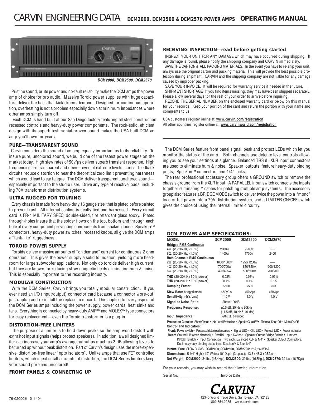
-ˆž50 30 22 19171513121110 9 8 7 6 5 4 3 2 1 0 dB -ˆž50 30 22 19171513121110 9 8 7 6 5 4 3 2 1 0 dB PROFESSIONAL STEREO POWER AMPLIFIER SERIAL NUMBER 120V~60Hz Slow Blow FUSE 8AG 700VA + -“-“BRIDGE-“-“ + -“ -“SPEAKER 2 SPEAKER 1 GND LIFT PARALLEL BRIDGE LIMITERS CH1 IN XLR PIN 1 GND PIN 2 POS PIN 3 NEG CAUTIONRISK OF ELECTRIC SHOCK DO NOT OPEN CAUTION - TO PREVENT ELECTRICAL SHOCK DO NOT DEFEAT THE SAFETY GROUND ON THE POWER CORD - DO NOT REMOVE COVER . WARNING - TO PREVENT FIRE OR SHOCK HAZARD DO NOT EXPOSE TO RAIN OR MOISTURE. REFER SERVICING TO QUALIFED PERSONNEL. PROTECT -ˆž50503030222219191717151513131212111110109 8 7 6 5 4 3 2 1 0 dB 0 dB DCM25002500 Watt Power Amp CLIP SIGNAL -ˆž50503030222219191717151513131212111110109 8 7 6 5 4 3 2 1 0 dB 0 dB POWER CHANNEL ONE CHANNEL TWO CLIP SIGNAL FRONT PANEL 1. MOUNTINGSturdy one piece 12 gauge steel face plate accomodates standard 19 rack installation. The rack mount- ing holes are designed on ISO standard spacing. Four 10-32 x .5 phillip machine screws are normally used to secure the amp. Rear support brackets are not required. 2. POWER SWITCHCheck the power amp connections and verify the AC line power source before engaging the POWER switch. The yellow LED unmistakably indicates that all circuits are properly powered up. Yellow is used so the operator can see the red indicators (clipping or protect) from a distance. 3. CHANNEL LEVEL CONTROLA precision input LEVEL attenuator is used to adjust the volume levels. To deliver the amps maximum power without reducing the headroom of the signal source, the level controls should be turned full on. 4. CHANNEL SIGNAL INDICATORThe green SIGNAL LED indicators will start to flash when there is a signal passing to your speakers (-30dBµ). This lets you know when the amp is passing a signal to your speaker connectors. 5. CHANNEL CLIP INDICATORThe red CLIP LED indicators will start to flash when each channel has reached its maximum output. Occasional flashing caused by lower bass frequencies is OK. However, consistent flashing caused from higher frequencies may damage high frequency drivers (excessive distortion). This does not cause damage to the amp. 6. COOLING VENTS/FANUpon rack installation, the rear of the amp must be fully exposed to room temperature air. The sur- rounding air should not be warmer than 120°F or the thermal protection could activate the PROTECT LED. The front cooling vents are not to be restricted from exhausting the warm air. 7. PROTECT LED INDICATOR The red PROTECT LED provides the operator with information about the status of the amplifier. The PROTECT LED can come on under 3 different conditions (when this happens both channels are muted by disconnecting the output speaker relays protecting your speakers); 1) During power-up, the amplifier stays in a muted state for approx. 3 sec until it determines that everything is functioning normally (no output shorts or over temp conditions). 2) When the output load draws excessive current or a direct short is detected caused by a shorted speaker cable or speaker system, the RED PROTECT LED will illuminate. Reset this condition by turning the amp off for two seconds and then on again. Check for shorted cables and the total speaker system impedance connected to each channel. 3) Overheating is usually determined when the amp stops in the middle of a performance and the PROTECT LED comes on. If this is the cause, leave the amp on for the fan to cool the amp down. The amp will automatically reset within 1 to 3 minutes. The PROTECT LED will turn off when ready. Check for the following conditions; a) The rear intake air is restricted, b) The intake air is extremely warm, c) The front exhaust vents are restricted, or d) Excessive speaker load (try other speakers or remove speakers if you have more than one connected to each channel). The minimum imped- ance is 2 ohms per ch or 4 ohms BRIDGED. DCM2570 minimum load is 4 ohms per ch or 8 ohms BRIDGED. REAR PANEL 8. CHANNEL INPUTS AND THROUGHBalanced or Unbalanced 1/4 TRS inputs can be used along with the balanced XLRs. The male THROUGH XLR connector carries the same signal as the female XLR to daisy chain channels or additional amps. XLR pin configuration: Pin 1: Grounded through the GROUND LIFT switch, Pin 2: positive Bal. signal and Pin 3: negative Bal. signal. 9. PARALLEL OR Y INPUTSThe rear PARALLEL switch IN allows you to drive both channels from either input in which a signal entering any input will be available on both channels eliminating Y adapters. 10. INPUT GROUND LIFTMany times sound systems are connected in such a manner to cause a grounded loop with the inputs which result in audible hum. The input GND LIFT (1/4 & XLR) switch on the rear panel will help eliminate this problem. If not, another way to eliminate ground loops is to install Carvins MTF55 Ground Lifter between the amplifier input and the signal source. This isolates the input ground from the AC power ground. 11. LO CUT (DCM2500, DCM2570) The LO CUT switch inserts a 40Hz, 3rd order, high pass filter. This will remove sub audio frequencies from damaging speakers and wasting inaudible power. It is active when the switch is pushed IN. 12. LIMITERS To activate the LIMITERS, engage the rear limiter switch to the IN position. The built-in optio limiters are recommended to hold down peaks that could cause early distortion. This will help to raise the average power so that you can get more output from each channel. To check the effectiveness of the limiters when the channel starts to distort (under full output), engage the limiters and hear the reduction of the distortion. If the distortion stops, you can try to turn the channel up for more power. The lower bass frequencies are most affected. WARNING: Do not check in an environment where the sound level could damage your ears! 13. SPEAKER 1/4 AND SPEAKON-„¢ OUTPUTS The standard 1/4 SPEAKER jacks are offered for low power applications. Speakon-„¢ connectors are pro- vided for high power application. Secure the Speakon-„¢ connection by turning to the right. The center Speakon-„¢ is for Bridge only. Turn the amp off before connecting your speakers. DCM 2570 minimum load 4 ohms 14. BINDING POST OUTPUTSFor other high power speaker connections, use the rear BINDING POSTS to connect your speakers. Wire sizes up to 7 gauge (50 amps) can be inserted into the binding post side holes. Larger cable can be used with banana plugs which plug into the end of the binding posts (remove colored caps from the top of the binding post). Binding posts are spaced on ISO standards. Use the two center RED binding posts to BRIDGE both power amps (see 15 BRIDGE MODE). 15. BRIDGE MODE- 25V/70V DISTRIBUTION SYSTEMS The DCM Series can be operated in bridge mode if you require a 25V / 70V distribution speaker system or a high powered mono (single channel) amp, which can double your power into a single load. With your amp off, push IN the rear (recessed) BRIDGE switch after you have made your connections to either the center bridge Speakon-„¢ or the rear center RED binding posts (ch 1 is + and ch 2 is -). Select carefully or damage may result to your speakers. This is why the switch has been recessed. No other speaker connec- tors or binding posts can to be used at the same time! The INPUT and LEVEL is handled by channel 1. Channel 2 is non-operational. The minimum speaker impedance is 4 ohms. CAUTION: The power developed by bridging your amp can destroy most speaker systems! DCM2570 minimum load is 8 ohms in BRIDGE 16. AC POWERYour amp is designed to run on either 120V 60 Hz or 240V 50Hz depending on the model purchased. The voltage range for 120V model is 95V to 132V and for 230V model it is 195V to 255V. The rear heavy- duty AC receptacle will accept a standard grounded AC cord that is designed for your country. Be sure to check your power source before plugging into a grounded (3 prong) outlet. Never defeat the grounded connection or electrocution may result! Firmly push the power cord all the way into its recepticle. In the case of a blown fuse; unplug the amp, remove the lid and replace the fuse located in the back corner above where the AC cord connects to the circuit board. FUSE:The fuse is located within the main chassis above the AC connector mounted on the rear, inside the PC card. Normaly if the fuse fails, the amp will require service. See spec. chart for fuse values. NOTE: Each amp will require a dedicated circuit if you are driving the amp to its full output. There will be a sustained loss of power if the AC voltage falls below the rated 120V or 230/240V. Use a heavy gauge power cable and power source. 6 FRONT & REAR PANEL CONTROLS WARNING This product produces high sound pressure levels that could damage your hearing. Use with caution. 1 5 15 12 10 16 4 3 7 2 6 13 8 14 911

Page 2

SHIELD -NEG.3 1 2 GND + SIGNAL (BAL.) Speakon-„¢ Tw i st-Lok HousingContact InsertCable ClampSecuring Hub - Connection Configuration: Black (1+) / positive White (1-) / negative Red (2+) / positive Green (2-) / negative - Solder wires in contacts or use hex screws provided. - Slip "Securing Hub" then "Cable Clamp" over cable before attaching wires. 1+1- 2+2- Solder tinned wires 1/4" Strip cable insulation back 3/4" SleeveRing Neg.Tip Pos. TRS 1/4 Balanced Tip-Ring-Sleeve TS 1/4 Unbalanced Tip-Sleeve Tip Sleeve Ring Tip XLR Tip Ground Ground Ring HELPFUL HINTS 1) NO SOUND FROM CH 2: The rear (recessed) BRIDGE switch has been inadvertently pushed in. 2) STEREO CHANNELS SOUND THE SAME: The rear PARALLEL switch has been inadvertently pushed in. 3)NO HIGH FREQUENCIES: Tweeters or midrange drivers have been damaged or blown from feedback or to much power.4) SYSTEM HUM: Switch the rear GND LIFT switch IN or OUT. If the hum is not eliminated, then install Carvins MTF55 Ground Lifter between the amplifier input and signal source. This iso- lates the input ground from the AC power ground. 5) POOR SOUND (BASS): The speaker systems are wired out of phase to each other. To correct, reverse the wires on one speaker connector only and your sound, especially the bass response will improve. - SIGNAL (BAL.) TYPICAL STEREO SETUP MONO MAINS & MONITORS STEREO BIAMPING CHANNEL TWO HIGHPHASEMIDPHASELOWPHASE XC3000Electronic Crossover 1-800-854-2235 www.carvin.com INTERNAL FUSE 90-250 VAC 10 VA ~50-60HZGND LIFT CHANNEL ONE HIGHPHASEMIDPHASELOWPHASEMONO[ LOW 1+2 ] SWITCHABLE TO MONO [ LOW 1+2] PROFESSIONAL STEREO POWER AMPLIFIER SERIAL NUMBER 120V~60Hz Slow Blow FUSE 8AG 700VA + -“-“BRIDGE-“-“ + -“ -“SPEAKER 2 SPEAKER 1 GND LIFT PARALLEL BRIDGE LIMITERSCH1 IN XLR PIN 1 GND PIN 2 POS PIN 3 NEG CAUTIONRISK OF ELECTRIC SHOCK DO NOT OPENCAUTION - TO PREVENT ELECTRICAL SHOCK DO NOT DEFEAT THE SAFETY GROUND ON THE POWER CORD - DO NOT REMOVE COVER . WAR NI NG - TO PREVENT FIRE OR SHOCK HAZARD DO NOT EXPOSE TO RAIN OR MOISTURE. REFER SERVICING TO QUALIFED PERSONNEL. PROFESSIONAL STEREO POWER AMPLIFIER SERIAL NUMBER 120V~60Hz Slow Blow FUSE 8AG 700VA + -“-“BRIDGE-“-“ + -“ -“SPEAKER 2 SPEAKER 1 GND LIFT PARALLEL BRIDGE LIMITERSCH1 IN XLR PIN 1 GND PIN 2 POS PIN 3 NEG CAUTIONRISK OF ELECTRIC SHOCK DO NOT OPENCAUTION - TO PREVENT ELECTRICAL SHOCK DO NOT DEFEAT THE SAFETY GROUND ON THE POWER CORD - DO NOT REMOVE COVER . WARNING - TO PREVENT FIRE OR SHOCK HAZARD DO NOT EXPOSE TO RAIN OR MOISTURE. REFER SERVICING TO QUALIFED PERSONNEL. Left Input Left Low Out Left High OutRight High Out Right Low Out Right Input STEREO CROSSOVER Suggested settings Low Frequency Amp High Frequency Left LowsRight Lows Right Highs Left Highs PROFESSIONAL STEREO POWER AMPLIFIER SERIAL NUMBER 120V~60Hz Slow Blow FUSE 8AG 700VA + -“-“BRIDGE-“-“ + -“ -“SPEAKER 2 SPEAKER 1 GND LIFT PARALLEL BRIDGE LIMITERS CH1 IN XLR PIN 1 GND PIN 2 POS PIN 3 NEG CA UTIONRISK OF ELECTRIC SHOCK DO NO T OPEN CAUTION - TO PREVENT ELECTRICAL SHOCK DO NOT DEFEAT THE SAFETY GROUND ON THE POWER CORD - DO NOT REMOVE COVER . WARNING - TO PREVENT FIRE OR SHOCK HAZARD DO NOT EXPOSE TO RAIN OR MOISTURE. REFER SERVICING TO QUALIFED PERSONNEL. For (stereo) the PARALLEL switch must be OFF (OUT). Ch 1 Left Ch 2 Right BRIDGE switch must be OFF (OUT). Right Full Range Left Full Range PROFESSIONAL STEREO POWER AMPLIFIER SERIAL NUMBER 120V~60Hz Slow Blow FUSE 8AG 700VA + -“-“BRIDGE-“-“ + -“ -“SPEAKER 2 SPEAKER 1 GND LIFT PARALLEL BRIDGE LIMITERSCH1 IN XLR PIN 1 GND PIN 2 POS PIN 3 NEG CA UTIONRISK OF ELECTRIC SHOCK DO NO T OPENCAUTION - TO PREVENT ELECTRICAL SHOCK DO NOT DEFEAT THE SAFETY GROUND ON THE POWER CORD - DO NOT REMOVE COVER . WARNING - TO PREVENT FIRE OR SHOCK HAZARD DO NOT EXPOSE TO RAIN OR MOISTURE. REFER SERVICING TO QUALIFED PERSONNEL. MainsMonitors Mains Ch 1 Main MixCh 2 Monitor Mix BRIDGE switch must be OFF (OUT). The PARALLEL switch must be OFF (OUT). 25V OR 70V DISTRIBUTION SYSTEM BRIDGED MONO PROFESSIONAL STEREO POWER AMPLIFIER SERIAL NUMBER 120V~60Hz Slow Blow FUSE 8AG 700VA + -“-“BRIDGE-“-“ + -“ -“SPEAKER 2 SPEAKER 1 GND LIFT PARALLEL BRIDGE LIMITERSCH1 IN XLR PIN 1 GND PIN 2 POS PIN 3 NEG CAUTIONRISK OF ELECTRIC SHOCK DO NOT OPENCAUTION - TO PREVENT ELECTRICAL SHOCK DO NOT DEFEAT THE SAFETY GROUND ON THE POWER CORD - DO NOT REMOVE COVER . WARNING - TO PREVENT FIRE OR SHOCK HAZARD DO NOT EXPOSE TO RAIN OR MOISTURE. REFER SERVICING TO QUALIFED PERSONNEL. PARALLEL switch OFF (OUT). To signal socket XLR or 1/4" 2 or 3 cond. shielded Activate the BRIDGE switch (IN). Control the level by Ch 1 (Ch 2 does not function.) Ch 1 Input Single speaker or system connected in BRIDGE mode. Minimum imp. 4-„¦ Use either the Bridged Speakon-„¢ connector or the binding posts. No other connections can be used while in Bridged mode. PROFESSIONAL STEREO POWER AMPLIFIER SERIAL NUMBER + -“-“BRIDGE-“-“ + -“ -“SPEAKER 2 SPEAKER 1 GND LIFT PARALLEL BRIDGE LIMITERSCH1 IN XLR PIN 1 GND PIN 2 POS PIN 3 NEG 25V or 70V Distribution System: Wattage of transformer (TAP) divided by total wattage of Amp = Number of transformer/speaker(s) that can be hooked up. + 16 8 4 C 15w 7w 3w 1w C + 16 8 4 C 15w 7w 3w 1w C 6)DEDICATED CIRCUIT BREAKER: Each amp will require a dedicated circuit breaker for its full output. There will be a sustained loss of power if the AC voltage falls below the rated 120V or 230/240V input.