Carvin dca 800 service manual

This is the 25 pages manual for carvin dca 800 service manual.
Read or download the pdf for free. If you want to contribute, please mail your pdfs to info@audioservicemanuals.com.

Page: 1 / 25
left right
carvin dca 800 service manual

Extracted text from carvin dca 800 service manual (Ocr-read)


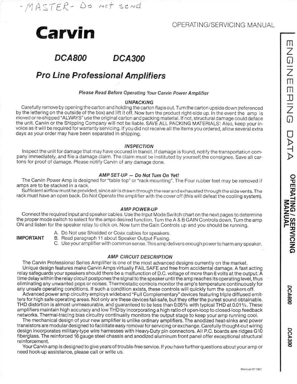
Page 1

-,rm:;rg-« Do ~~" 4

Carvin

DCA 800 DCA 300

Pro Line Professional Amplifiers

Please Read Before Operating Your Carvin Power Amplifier

UNPACKING
Carefully remove by opening thecarton and holding the canon flaps out. Turn the carton upside down (referenced
by the lettering on the outside of the box) and lift it off. Now turn the product right-side up. In the event the amp is
moved or reshipped ALWAYS" use the original carton and packing material. If not, structural damage could deface
the unit. Carvin or the Shipping Company will not be liable. SAVE ALL PACKING MATERIALS! Also, keep your in-
voice as it will be required for warranty servicing. If you did not receive all the items you ordered, allow several extra
days as your order may have been separated in shipping.

INSPECTION
Inspect the unit fordamage that may have occured in transit. lf damage is found, notify the transportation com-
pany immediately, and file a damage claim. The claim must be instituted by yourself,the consignee. Save all care
tons for proof of damage. Please notify Carvin of any damage done.

AMP SET-UP - Do Not Turn On Yet!
The Carvin Power Amp is designed for table top" or rack mounting". The Four rubber feet may be removed if
amps are to be stacked in a rack.
Sufficient airflow must be provided, since air is drawn through the rear and exhausted through the side vents.The
rack must have an open back. Do Not Operate the amplifier with the cover off (this will defeat the cooling system).

AMP POWER-UP
Connect the required input and speaker cables. Use the Input Mode Switch chart on the next pages to determine
the proper mode switch to select for the amps desired function. Turn the A & 8 GAIN Controls down. Turn the amp
ON and listen for the speaker relay to click on. Now turn the Gain Controls up and you should be running.

A. Do Not use Shielded or Coax cables for speakers.
IMPORTANT B. Read paragraph 11 about Speaker Output Fusing.
C. Use your amplifier with common sense. This amp delivers enough powerto harm any speaker.

AMP CIRCUIT DESCRIPTION

The Carvin Professional Series Amplifier is one of the most advanced designs currently on the market.

Unique design features make Carvi n Amps virtually FAIL SAFE and free from accidental damage. A fast acting
relay safeguards your speakers should there be a malfunction of DC. voltage of more than 8 volts at the output; A
time delaywithin the relay circuit postpones the signal to the speaker until the amp reaches its operating level, thus
eliminating any unwanted pops or noises. Thermostatic controls monitor the amps temperature continuously for
any unsafe operating conditions. If such a condition exists, these controls will quickly turn the speakers off.

Advanced power amp circuitry employs wideband Full Complementary" devices featuring triple diffused emit-
ters for high safe operating areas. Not only are these devices fail-safe, but they offer the purest sound obtainable.
THD distortion is almost unmeasurable, and guaranteed to be less than 0.05% with typical THD at 0.01 %. These
amplifiers maintain high accuracy and low THD by incorporating a high ratio of open~loop to closed-loop feedback
networks. Thermal-tracing bias circuitry continually monitors the output stage to keep your amp running cool.

The mechanical design of your new amplifier is unlike ordinary amplifiers. The anodized heat-sinks and power
transistors are modular designed to facilitate easy removal for servicing or exchange. Carefullythought-out wiring
design incorporates military-type wire harnesses with Heavy-Duty pin connectors. All PC. boards are ridges G10
fiberglass. The reinforced 16 gauge steel chassis and anodized aluminum front panel offer exceptional structural
reinforcement.

Your Carvin amp is designed to give years of trou ble-free service. If you have further questions about your amp or
need hook-up assistance, please call or write us.

Manual D1198I

OPERATI NG/SERVICI NG MAN UAL

V_LVCI SNltziElElle-DNE I

'IVflNVlN
SNIOIAHEIS / SNIlVHEIdO

OO8VOU

OOSVOCI

Page 2

Amplifier Operation

. O
. a" s
. Bl @ .
mun A uvu E . .
. ..
FrmlPanet
FRONT PANEL

1. POWER SWITCH Push for ON. A speaker protection relay will engage the speakers within 3 seconds to mute any turn-on"
transients or pops. Push again for OFF. The protection will instantly disengage speakers eliminating any "turn-off" pops or noise.

2. The LED above the power switch denotes that there is power to the amp when turned on.

3. A A B LEVEL GAIN CONTROLS allow the operator to adjust the sensitivity of the power amp to match the mixer output levels.
These Gain controls do not limit the amps output. Maximum output can be easily obtained at settings less than Full On. To proper-
ly adjust the Gain controls: set amplifier Gain to zero, set mixer or pro-amp master volume at mid position and raise amplifier gain
for maximum volume desired. After adjustment, use mixer or pre-amp master volume control to control the power amplifier. Note:
This usually gives the best signal-to-noise ratio.

4. LED CLIP INDICATORS are featured on both the DCA800 and DCASOO amplifiers. These LED clip" indicators will start to
flash when the amp runs out of clean power, giving you avery accurate indication when distortion starts. These indicators monitor
the amps feedback circuits which will cause the Clip LEDs to light at the instant your amplifier begins to clip. These clip" in-
dicators also function as a method to monitor the thermal condition of your amplifier. Also, an inadvertent shortoircuited output
(with signal) will cause the CLIP LED to remain on until the short is removed.

5. TH ERMOSTATIC CONTROLS are provided on each modular HeatSink assembly to turn the amp off if it should ever become
over heated because of improper ventilation. The clip" indicators are designed to light if this condition should ever exist.

REAR PANEL

6. LINE CORD All Carvin equipment is supplied with S-conductor line cords. ending in grounding type plugs. This arrangement
will greatly reduce the possibility of electrical shock when used with proper Groonductor outlets.

7. The GROUND SWITCH enables the operator to remove the A.C. line ground off the chassis. This totally isolates the amps
ground system. Select this switch for the quietest hum position.

8. PRIMARY FUSE AND DCABOO VOLTAGE SWITCH. All DCABOO amplifiers are wired for 120 VAC and are fused at 15 amps
with an AGO type fuse. However, the DCA800 may be convened to 240 VAC by removing the Hole Plug (between the line cord and
pri fuse), inserting a small screwdriver and selecting the proper voltage. The DCA300 requires an AGC 5 amp fuse.

9. FAN SWITCH for the DCABOO models only. A 2 position switch is provided for diverse applications. Select the LO position
under average high power operations. Select the HI position if the amp is to be used under heavy continuous loads. Carvin
employs a computergrade fan. However, you will notice some increase of fan noise in time. This is normal. These fans are design-
ed for continuous operation.

10. SPEAKER OUTPUTS Each amplifiers output has two Phone Jacks (wired in parallel) along with Dual 25 amp Banana
plugs. Red denotes Positive and Black denotes negative speaker outputs.

11. OUTPUT FUSES are offered for added speaker protection However, the 10AGC fuse supplied with your amp is too large to
protect any speaker. This large value Is supplied because some speaker systems like Carvin have their own protection. If you wish
protection, remove the 10AGC and install the following suggested fuse values.

A./AAGC Fuse for Horn Drivers up to 50 Watts (Bi-Amped).
B. 1AGC'Fuse for Horn Drivers up to 50 Watts using a Passive Crossover.
C. 2/2AGC Fuse for Woofer rated between 100 and 150 Watts.
D. 21/zAGC Fuse for 2 or 3 Way speaker system rated at 100 Watts.
These approximate fuse values are for 8 Ohm speakers. Double all fuse values when paralleling speakers speakers together.
CAUTION This amplifier is powerful enough to destroy any speaker. The above fuse recommendations can only be used as a
guide. Your requirements may be different.
PROCEED WITH CAUTION: WE ASSUME NO RESPONSIBILITY FOR ANY DAMAGE DONE TO SPEAKERS REGARDLESS OF
CIRCUMSTANCE.

12. AdMPLIFIER BRIDGING is only recommended for high powered monaural applications. To bridge your amp follow the below
proce ures.

A. Connect your speaker load across both Red" speaker terminal posts (A&B Channels). The RED terminal post A is positive and
the RED terminal post 8 red post is negative. The Black terminals are not used.

B. Locate the rubber cap next to the Fan Switch. Remove this cap and with a screw driver move the switch down" to Bridge Mode.
C. Plug your input into the A amplifier. Use the Again control for setting your levels. Note: The B gain control must also be turned to
the Full On position.

13. INPUTS Your amplifier will accept either a Balanced Line through the USP connector or an Unbalanced Line through the
Phone Jack. The DSF ConnectorWirlng: Pin 1 is Ground, Pin 2 is Negative Bal., Pin3 is Positive Bal.The Balanced cirucit features
a transformerless Differential Amplifier designed for balanced lines down to 150 Ohms. lmpedances as high as 50,000 Ohms can
also be used but with some loss of high frequencies. Thetransformerless design incorporated offers superiorTHD and Frequency
Response over conventional inputs.