Carvin bx 1500 owners manual

This is the 2 pages manual for carvin bx 1500 owners manual.
Read or download the pdf for free. If you want to contribute, please mail your pdfs to info@audioservicemanuals.com.

Page: 1 / 2
left right
carvin bx 1500 owners manual

Extracted text from carvin bx 1500 owners manual (Ocr-read)


Page 1

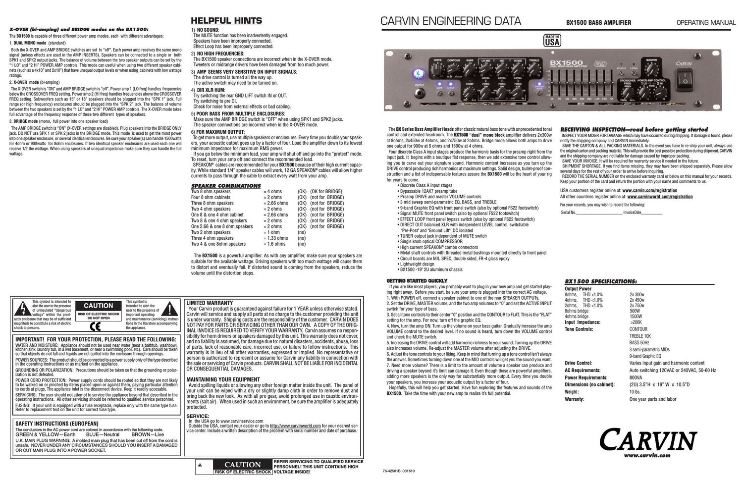
FRONT PANEL CONTROLS REAR PANEL CONTROLS 17 22 23 21 18 20 1. INPUT JACK The 1/4" phone jack is a high impedance instrument input designed to handle both active and passive basses in connection with the ACTIVE switch. 2. BLUE JEWEL LIGHT AND POWER SWITCHThe power switch turns on the amplifier and is indicated by the large blue jewel light over the input jack. 3. DRIVE CONTROLThe DRIVE control adjusts the input level to the class A preamps. The DRIVE control serves two pur- poses. DRIVE can be used to adjust the input sensitivity for the differences in bass pickups. DRIVE will also change the harmonic content of your sound. Turning the knob closer to 10 will create a more over- driven tone. The DRIVE will also change the volume of the amplifier, so use it in combination with the MASTER control to achieve the desired volume. 4. MUTE SWITCHThe MUTE switch turns off the output of the amplifier. A blue LED indicates the MUTE switch is on. The MUTE switch is ideal for changing basses and silent tuning on stage, since the rear tuner output is never muted. The mute feature can also be switched with an FS22 footswitch. 5. ACTIVE SWITCHFlip the ACTIVE switch to the DOWN position for standard bass pickups. If your bass uses a battery with an onboard active preamp, put the switch in the UP position. A blue LED indicates the ACTIVE switch is on. 6. CONTOUR CONTROLThe CONTOUR control provides a variable mid range scoop. When this control is set to FLAT there is no change to the mid range frequencies. As you turn the contour control clockwise, the mid range is scooped at the center frequency at 250Hz. When the CONTOUR control is set to maximum the mid-range is cut by -9dB at 300Hz. 7. BASS AND TREBLE TONE CONTROLSThe BASS and TREBLE controls are custom shaped tone controls designed to deliver punchy lows and crisp highs for a variety of bass sounds. When a control is turned to the right it boosts the signal and when turned to the left cuts the signal. The affected frequencies for the BASS start at 80Hz and can deliver a great deal of volume. Be careful not to distort the output or overpower the low end of your speakers. The affected frequency for the TREBLE control begins at 5kHz. 8. SEMI-PARAMETRIC MID SWEEP TONE CONTROLS (LEVEL & FREQ)These three EQs can take some time to learn how to use. Start with the LO MID sweep. The FREQ con- trol does not function if the GAIN control is set in the center 0 position. To demonstrate, turn the GAIN to the right for full boost. Now play your bass and turn the FREQ control from left to right and notice the how the added mids change frequency. Now turn the GAIN to the full left and turn the FREQ control again and notice the mids disappear at different frequencies. Try this with the MID and HI MID also. As you can hear, there are many variables, so write down some of the settings for future reference. The mid sweep system controls can be very effective to fine tune your overall sound. 9. COMPRESSOR (COMP) For some people, a compressor is a new feature. What it basically does is reduce the volume of the incoming signal as it reaches a preset maximum level. As the COMP knob is turned up (clockwise), the compressor lets a lower percentage of peak signals to pass through. This percentage is called the com- pression ratio. When the knob is at the off position (full counter-clockwise) the ratio is 1:1, where all of the input signal passes through the compressor without being affected. At the MAX setting, the com- pression ratio is 3:1.The advantage of a compressor is to the reduce peaks and other sudden loud parts (transients) of your playing so you can increase your overall volume. For example, in slap bass playing, the plucked notes can put out peaks that would distort the amplifier at normal playing volumes. If the amps volume was adjusted for these peaks, the rest of the notes would be too quiet to hear with the band. When the com- pressor is adjusted to where the LED comes on for loud peaks, the amplifier can be played louder with- out distortion. Its like having someone re-adjusting the volume of the amplifier to prevent distortion when the peaks occur. The compressor circuit in the BXseries is also internally connected to the power amplifier. When the amplifier reaches peak clipping levels it activates the compressor and reduces the output signal. This helps prevent the amplifier from clipping and protects the speakers. 10. 9 BAND GRAPHIC EQUALIZERThe 9 band graphic EQ has been designed with center frequencies most requested by professional bass players. This EQ can be used to fine tune the tonal content of the amps output. Since the graphic EQ is switchable with either the optional FS22 footswitch or the EQ switch on the front panel, it can be used during passages of a song when the bass needs to punch through the mix. Musicians that play more than one bass on stage will also find this useful to get the sounds they desire out of each instrument. The BLUE LED located above the GRAPHIC EQ IN switch signifies when the graphic EQ is working. NOTE : When the front panel GRAPHIC EQ switch is off, it cannot be turned on with the footswitch. 11. EFFECTS LOOP SWITCH The green LED above the front panel EFFECTS switch indicates when the EFFECTS LOOP is active. When the EFFECTS switch is off the EFFECTS LOOP is bypassed. The signal is still present at the SEND jack, but the RETURN is not active. The EFFECTS LOOP can also be switched using the optional FS22 footswitch. NOTE : When the EFFECTS switch is off, the loop cannot be turned on with the footswitch. 12. ELECTRONIC CROSSOVER The electronic X-OVER is used for a bi-amped speaker configuration. When the X-OVER switch is ON, the BX1500 is in bi-amp mode and the BLUE LED above it will be lit. To select the crossover frequency, rotate the FREQ control knob until the desired frequency is obtained. Low frequencies go to AMP1, and high frequencies go to AMP2. This allows speakers designed for specific frequencies to be utilized to their fullest potential, and allows the user even greater control over the tone of thier rig. To start, try set- ting the FREQ at 300Hz. NOTE : BI-AMPING does not necessarily deliver the most volume from your system. 13. MASTER VOLUME Use the MASTER to control the overall volume of the amplifier. Reduce the MASTER level if clipping occurs as indicated by the PEAK LEDs (see #15). Using the COMPRESSOR will also help prevent clip- ping. The MASTER control also affects the HEADPHONE output. 14. POWER AMP CONTROL The 1 LO and 2 HI levels control the volume to the individual amps. These are used to balance the low and high frequency speaker cabinets when in X-OVER bi-amping mode. To set the balance, bring up the 1 LO knob until the desired volume level is reached. Now bring up the 2 HI knob until the desired bal- ance has been achieved. Use the MASTER volume control to set the overall volume. 15. PEAK LEDS The red PEAK LEDs are clipping indicators for the amplifier(s). If the amps are clipping use the MASTER to reduce the level. The COMPRESSOR may also serve to help prevent clipping. Be sure not to run the amps with heavy continuous clipping (PEAK LEDs ON) or your speakers could be damaged. 1 4 5 8 10 14 15 9 19 16 25 24 26 2 6 8 3 7 7 11 13 2 16. DI LEVEL (DIRECT OUT) The DI LEVEL controls the output level of the XLR DIRECT OUTPUT. The DI level is not affected by the MASTER level. 17. DIRECT OUT PRE/POST SWITCH AND GROUND LIFT SWITCH The direct out PRE/POST switch allows the choice of either a simple buffered signal straight from the input jack (PRE mode) or a processed signal including the Drive, Compressor, Tone, Graphic EQ, and Effect Loop processing (POST mode). If a hum occurs when connecting the XLR to a mixer, try using the GND LIFT switch. The GND LIFT switch lifts the ground pin 1 of the XLR to 100 ohms above chassis ground. 18. DIRECT OUT XLR JACK The DIRECT OUT XLR jack provides a balanced independent output for going direct to the main PA or recording input. The front MASTER control does not affect the output level. The XLR is protected against Phantom power (DC voltage) on cables coming from mixer inputs. 19. FOOTSWITCH AND CONFIGURATION SWITCHES The optional FS22 footswitch can be used to remotely control 2 of these 3 features: MUTE, graphic EQ, or EFFECTS LOOP bypass. The two configuration switches set the functions of the FS22 footswitch. The left switch controls the footswitch connected to tip of the 1/4 plug and the right switch controls the footswitch connected to the ring of the plug. There are four configurations: The rear LEDs near each switch work with the front LED of the Effects loop and Graphic EQ. These LEDs will only light when the feature is turned ON by the footswitch. Use them to verify the configu- ration switches are in the desired positions. Any standard footswitch with a stereo (TRS) plug will work. 20. EFFECTS LOOP (SWITCHABLE)The SEND jack is the output of the preamp and is designed to deliver the proper level for the input of an external effects processor. The SEND signal source is after the TONE CONTROLS and COM- PRESSOR (#7, #8, & #9). The RETURN jack is designed to receive signals from the output of an external effects processor. When a signal is plugged into the RETURN, it breaks the connection between the preamp and the internal power amp. The RETURN signal goes through the GRAPHIC EQ (if active) and MASTER controls to the power amp(s). The EFFECT LOOP can be bypassed with the front panel switch (see #11) or optional FS22 footswitch (see #19). 21. AMP INSERT JACKS The AMP INSERT jacks are TRS (Tip-Ring-Sleeve). The TIP is the SEND and the RING is the RETURN. Using a TRS (Tip-Ring-Sleeve) insert cable, the preamp signal can be sent out via the TIP to an external proces- sor and then returned to the internal power amp via the RING. If a standard (Tip-Sleeve) instrument cable is used, the signal can be routed from the preamp to an external power amp. These insert jacks break the signal to the internal power amplifier. Use the MASTER (or AMP 1 & 2) controls on the front panel for SEND level adjustments. When the X-OVER is OFF, both outputs receive the same full range signal. When the X-OVER is ON, AMP 1 receives the low frequency signals and AMP2 receives the high frequency signals. 22. TUBE BYPASSThe TUBE BYPASS SWITCH removes the 12AX7 preamp tube from the signal path. 23. TUNER LINE OUT JACK (UNMUTED) The TUNER LINE OUT jack is provided as a place to connect a tuner. This output is unaffected by the MUTE function so you may tune your bass quietly while using the MUTE. 24. SPEAKER OUTPUTS (SEE IMPEDANCE CHART ON BACK PAGE)The BX1500 uses three combination 1/4 and SPEAKON® speaker output connectors. Multiple speak- ers can be attached by chaining cabinets together, so long as the total impedance is not below 2 ohms for each SPK 1 or SPK 2 jack and 4 ohms for the BRIDGE ONLY jack. 1/4 speaker cables can be plugged into the center of the green SPEAKON® jacks . The SPEAKON® connector is highly recommended for BRIDGE mode (see #25). 25. AMP BRIDGE SWITCH AND LEDThe AMP BRIDGE switch enables the full power of both amps in the BX1500 to be sent to the single BRIDGE ONLY jack. The LED will illuminate to indicate BRIDGE mode. Total minimum impedance is 4 ohms. DO NOT connect speakers to the SPK 1 or SPK 2 when in AMP BRIDGE mode. NOTE : In the AMP BRIDGE mode, the MASTER and POWER AMP1 controls adjust the output volume. 26. AC POWER & FUSEInsert the power cord into this jack and push until fully inserted. Plug the cord into a grounded 3 prong power source. No attempt should ever be made to use the amp without the ground connected. The FUSE is located internally on the circuit board. To check or replace the fuse, remove the power cord and the enclosure lid. If the fuse is blown repeatedly, it is likely the amp will require service. TIP switch setting RING switch setting footswitch 1 function footswitch 2 function TIP LED 1 (must be on) RING LED 2 (must be on) IN IN Effect Loop Graphic EQ GREEN BLUE OUT IN MUTE Graphic EQ off BLUE IN OUT Effect Loop MUTE GREEN off OUT OUT MUTE not used off off 12