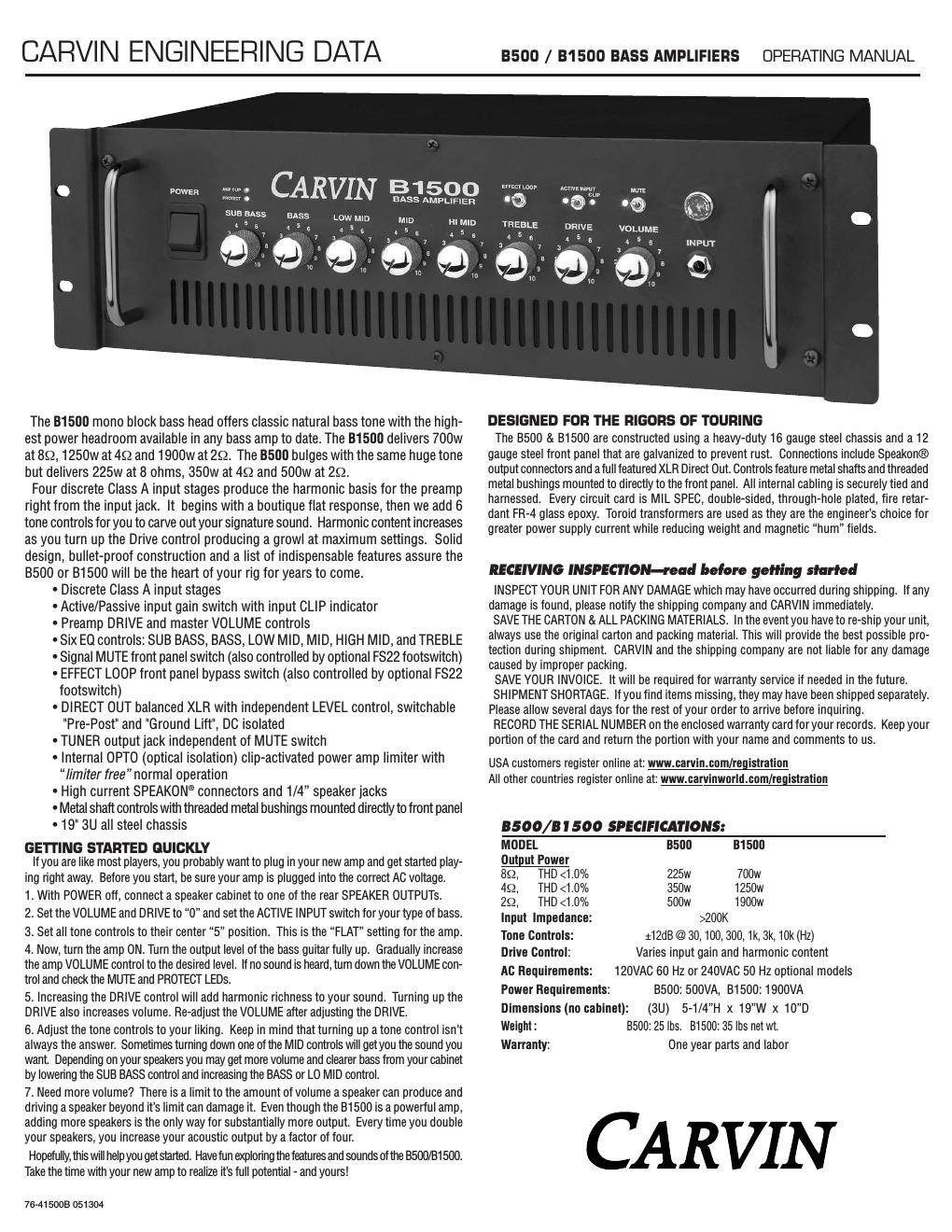
Carvin b 1500 owners manual

This is the 4 pages manual for carvin b 1500 owners manual.
Read or download the pdf for free. If you want to contribute, please mail your pdfs to info@audioservicemanuals.com.

Page: 1 / 4
left right
carvin b 1500 owners manual

Extracted text from carvin b 1500 owners manual (Ocr-read)


Page 1

HELPFUL HINTS 1) NO SOUND FROM AMP: The MUTE function has been inadvertently engaged, speakers have been improperly connected or Effect Loop has been improperly connected. 2)NO HIGH FREQUENCIES: Tweeters or midrange drivers have been damaged from too much power. 3)WEAK BASS: The speaker systems are wired out of phase to each other. To correct, reverse the wires on one of the speaker connectors. 4) DIR XLR HUM: Try switching the rear GND LIFT switch IN or OUT. Check for noise from external effects or bad cabling. 1. INPUT JACKThe 1/4 INPUTjack accommodates both passive and active instruments. The high imped- ance Class A input stage offers enough headroom to perform without clipping even when used with high output active basses. Input gain is adjusted with the DRIVEcontrol (6) and the ACTIVE INPUTswitch (5). 2. VOLUME CONTROLThe VOLUMEcontrol adjusts the output level to the speakers. Adjusting the DRIVEcontrol will also change your output level. 3. MUTE SWITCH / LEDThe MUTEswitch will stop all output signals with the exception of the TUNER and EFFECT SENDsignals. The MUTEfunction can also be remotely controlled from the rear FOOTSWITCH jack using the optional FS-22footswitch. The blue LED next to the MUTE switch will light when- ever the amp is muted. The footswitch will have no effect if the front panel MUTE switch is on in the UP position. 4. CLIP LEDThe red CLIPLED indicates that the input is near clipping. Since the B1500/B500 preamp is designed with several Class Ainput gain stages and the ability to be overdriven, the CLIPLED monitors only the first input stage and will not indicate when the DRIVEcontrol is set to over- drive the preamp. To avoid input clipping, reduce the bass level or reduce the output level of devices placed between the bass and the input jack. 5. ACTIVE INPUT SWITCH / LEDThe ACTIVE INPUTswitch is used to match the input gain of the amp to instruments that contain active electronics. If the preamp is being prematurely overdriven, flip the ACTIVE INPUT switch to the ON position. If the output of your bass is low and you are not getting enough volume from the speakers, be sure the ACTIVE INPUTswitch is OFF and increase the DRIVE control. The blue LED indicates that the ACTIVE INPUT mode is ON. 6. DRIVE CONTROLThe DRIVEcontrol adjusts the input gain to the preamp and the level of harmonics in the signal. With the DRIVEcontrol set low, both input gain and harmonics are at a minimum for clean output. Increasing the DRIVEcontrol causes the Class A gain stages to introduce more harmonics resulting in a rich sound typical of vintage tube amps. With the DRIVEcontrol set near maximum, overdrive sounds can be produced. The DRIVEcontrol can be used with the ACTIVE INPUTswitch to get the sound you want. To reduce preamp overdrive while retain- ing the harmonics of a high DRIVElevel setting, turn the ACTIVE INPUTswitch ON or reduce the level on the bass guitar. Turning the ACTIVE INPUTswitch OFF will make the preamp over- drive easier. 7. TONE CONTROLSThe six TONE CONTROLS on the B500/B1500 are designed with the center frequencies most requested by professional bass players. To start, set each control at its center flat position (no tones are cut or boosted). Raise or reduce each control to get your desired tone. The SUB BASScontrol is centered at 30Hz. The BASScontrol is centered at 100Hz. The LO MIDcontrol is centered at 300Hz. The MIDcontrol is centered at 1kHz. The HI MIDcontrol is centered at 3kHz. The TREBLEcontrol is centered at 10kHz. 8. EFFECT LOOP SWITCH / LEDThe EFFECT LOOP switch engages the rear effects loop connections. The effects loop can be turned on with the EFFECT LOOPswitch on the front panel or by using the optional FS22 footswitch. When the front panel switch is in the UP position, the loop is engaged regardless of the footswitch. The status of the effects loop is indicated on the front panel by the BLUE LED next to the EFFECT LOOPswitch. See EFFECT LOOP SEND/RETURN JACKS #13. 9. AMP CLIP LEDThe AMP CLIPLED indicates that the power amp is being driven too hard . Reduce the volume level. 10. PROTECT LEDThe PROTECTLED indicates that the power amp has gone into one of its protect modes. 11. POWER SWITCH / (PROTECT RESET)Push the upper portion of the POWER SWITCH to turn the amplifier on. If the large blue power indicator is on but no sound is coming out of the speakers, the amp may have gone into one of its protection modes. To reset the amp, turn the power off for 30 seconds and then turn the amp back on. If the problem persists, check for; a) The speaker impedance is too low for the amp, b) bad speaker cable, c) damaged speaker or, d) blocked rear fan intake. 1 FRONT PANEL CONTROLS 2 3 45 6 7 8 9 10 11MUTE ACTIVEEFFECT LOOPPROTECT AMP CLIP5 4 3 2 1 01098 7 65 4 3 2 1 01098 7 65 4 3 2 1 01098 7 65 4 3 2 1 01098 7 65 4 3 2 1 01098 7 65 4 3 2 1 01098 7 65 4 3 2 1 01098 7 65 4 3 2 1 01098 7 6MUTE ACTIVEEFFECT LOOPPROTECT AMP CLIP5 4 3 2 1 01098 7 65 4 3 2 1 01098 7 65 4 3 2 1 01098 7 65 4 3 2 1 01098 7 65 4 3 2 1 01098 7 65 4 3 2 1 01098 7 65 4 3 2 1 01098 7 65 4 3 2 1 01098 7 6

Page 2

12. COOLING VENTSThe rear vents are for cooling the internal power amps. Provide a minimum 3 rear clear- ance for adequate ventilation. Blocking the air flow to these vents will cause the amp to ther- mally protect and turn the speaker relay off. If this happens, clear the obstruction first, keep the power on and turn the volume down allowing the amp to cool. The amp will engage the speaker relays when cooling conditions return to normal. 13. EFFECT LOOP SEND/RETURN JACKSTheEFFFECT LOOP- SENDand RETURNjacks are used to connect external effects into the B500/B1500 signal chain. The loop is inserted after the DRIVE and TONE CONTROLS but before the VOLUME control. To use the effects loop, connect the SEND jack to the input of the effects unit and connect the RETURNjack to the output of the effects unit. The effects loop can be turned on with the EFFECT LOOPswitch on the front panel or by using the optional FS22footswitch. When the front panel switch is in the UP position, the loop is engaged regardless of the footswitch. The status of the effects loop is indicated on the front panel by the BLUE LED next to the EFFECT LOOPswitch. 14. DIRECT OUT XLRThe DIRECT OUTXLR is a balanced output that can be configured in a number of different ways. The PRE / POSTswitch is used to select a pre or post preamp feed. In the PRE(OUT) position, a direct feed is taken off of the INPUTjack and is similar to using a direct input box at the bass guitar output. In the POST(IN) position, the feed is post the preamp section and contains all of the signal that is sent to the power amp and speakers. To set the output, use the DIRECT OUT LEVEL control. A GND/LIFTswitch is also available for the DIRECT OUT XLR jack. Set this switch for the lowest noise when using this output. When the GND/LIFTswitch is depressed, the signal ground is lifted from this jack thus eliminating any ground loops between the B500/B1500 direct out and the gear it is feeding. 15. FOOTSWITCHConnect the optional FS22footswitch to remotely control the MUTE function and the EFFECTS LOOP bypass. The first button on the FS22turns the MUTE on and off and the second button turns the EFFECTS LOOP on and off. Any standard footswitch with a stereo plug will work. 16. TUNER LINE OUT JACK (UNMUTED)The TUNER LINE OUTjack is provided as a place to hook up a tuner. This output is unaf- fected by the MUTE function so that you may tune your bass quietly. 17. SPEAKER OUTPUTSThe B500/B1500 amp contains four 1/4and two SPEAKON ®speaker output connectors. Multiple speakers can be attached to either the 1/4 or SPEAKON®jacks so long as the total impedance is not below 2-„¦. See SPEAKER COMBINATIONS AND OHMS chart. 19. INTERNAL FUSEIf there are high AC voltage surges or if the amp is used with excessive loads, the internal fuse will protect your amp from damage. If the fuse fails, remove the cover and replace with the proper replacement fuse. For 120 VAC models; B500-15 AMPand B1500-25 AMP250VAC slow blow. 240 VAC models; B500-10 AMPand B1500-15 AMP250 VAC slow blow. 20. AC LINE CORDAll B500/B1500 Series bass amplifiers are supplied with detachable three conductor AC line cords. Make sure the cord is securely inserted into the back of the unit. Never defeat the ground of the AC line cord. If you must plug into a two prong outlet, use a quality 3 to 2 prong grounded adapter and properly ground it. FOR MAXIMUM OUTPUT:A. To get more output, use multiple speakers or enclosures. Every time you double your speakers, your acoustic output goes up by a factor of four. Load the amplifier down to its lowest minimum impedance for maximum RMS power. B. To get the highest output from your B500/B1500 bass amp use two 4 ohm speak- ers. Plug two SPEAKON ®cables into the rear SPEAKER OUTPUT connectors or daisy- chain another SPEAKON®from speaker to speaker. Two 4 ohm speakers will give you a total impedance of 2 ohms, which is the maximum power from your amp. If you use more than two 4 ohm speakers, your amp will shut off and go into the protect mode. To reset, turn your amp off and connect only two 4 ohm speakers. C. SPEAKON ®cables are recommended for your bass rig because of their high current capacity. While standard 1/4 speaker cables will work, the CARVIN 12 GA SPEAKON ® cables will allow higher currents to pass through the cable to extract every watt from your B500/B1500 bass amp. REAR PANEL CONTROLS (INTERNAL FUSE) SPEAKER COMBINATIONS and OHMS ( -„¦): Four x 8-„¦cabinets = 2-„¦(OK) Three x 8-„¦= 2.66-„¦(OK) Two x 8-„¦= 4-„¦(OK) Two x 4-„¦= 2-„¦(OK) One 8-„¦and One 4-„¦cabinet = 2.66-„¦(OK) Two 8-„¦and One 4-„¦= 2-„¦(OK) One 2.66-„¦and One 8-„¦= 2-„¦(OK) Two x 2-„¦= 1-„¦(no) Three x 4-„¦= 1.33-„¦(no) Two x 4-„¦and One 8-„¦= 1.6-„¦(no) The B1500 is a very powerful amplifier. As with any amplifier, make sure your speak- ers are suitable for the available wattage. Driving speakers with too much wattage will cause them to distort and eventually fail. If distorted sound is coming from the speak- ers, reduce the volume until the distortion stops. 12 16 13 14 15 17 19 20cEFFECT LOOP RETURN SEND FOOTSWITCH TUNERTRS JACKSLEEVE - GND RING - MUTE TIP - EFFECT LOOPA USMADE IN THEB1500SPEAKER OUTPUTSPIN 1-“ NEG PIN 2+ & 2-“ not used PIN 1+ POS1900W 2 OHMS 1250W 4 OHMSSERIAL NUMBER2 OHMS MIN.LINE OUT120V 60Hz 1500VA INTERNAL FUSE700W 8 OHMSBASS AMPLIFIERqUNMUTEDDIRECT OUTLEVELGND POST LIFTPREc