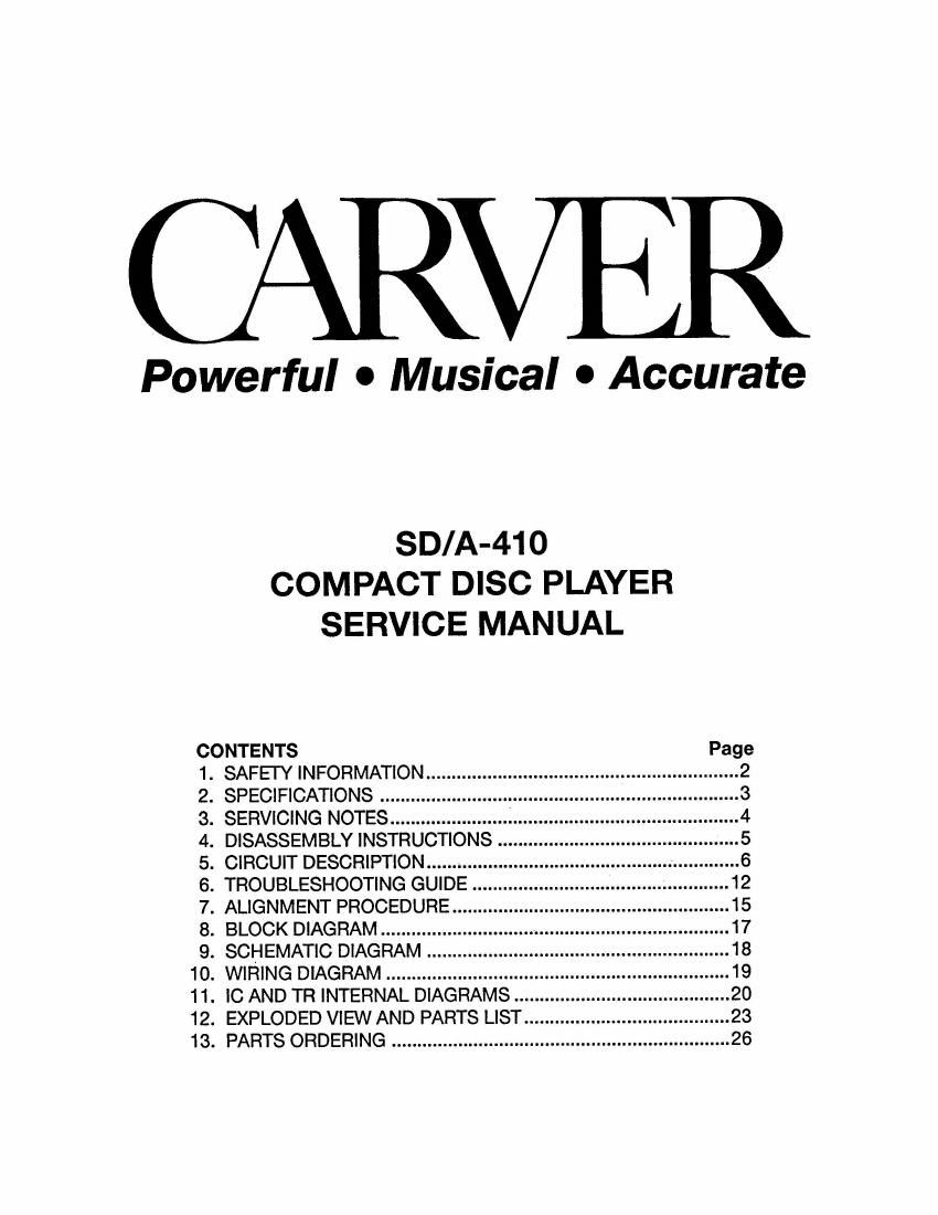
Carver SDA410 cd sm

This is the 28 pages manual for Carver SDA410 cd sm.
Read or download the pdf for free. If you want to contribute, please mail your pdfs to info@audioservicemanuals.com.

Page: 1 / 28
left right
Carver SDA410 cd sm

Extracted text from Carver SDA410 cd sm (Ocr-read)


Page 1

CARVER

Powerful 0 Musical - Accurate


SD/A-41 O
COMPACT DISC PLAYER
SERVICE MANUAL
CONTENTS Page
1. SAFEl'YlNFORMATION ............................................................. 2
2. SPECIFICATIONS ................... 3
3. SERVICING NOTES ............................. 4
4. DISASSEMBLYINSTRUCTIONS... ..... 5
5. CIRCUIT DESCRIPTION .......................... 6
6. TROUBLESHOOTING GUIDE ..12
7. ALIGNMENT PROCEDURE ........ ...15
8. BLOCK DIAGRAM ..................................... 17
9. SCHEMATIC DIAGRAM ....................... 18
10. WIRING DIAGRAM ................................................... 19
11. IC AND TR INTERNAL DIAGRAMS .............................. 20
12. EXPLODED VIEW AND PARTS LIST ................................ 23

13. PARTS ORDERING .................................................................. 26

Page 2

CARV 3R Corporation

SHIP TO: MAIL TO:
20121 48th Ave. West P.O. Box 1237
Lynnwood Wa. 98036 Lynnwood Wa. 98046-1237

(206) 775-6245

Published by:

CARVER Corporation
20121 48th Avenue West
Lynnwood, WA 98036

i (206) 775-6245

©1992 by CARVER Corporation
All Rights reserved.
Printed in Korea

; No part of this publication may be reproduced, stored In a data base or retrieval system, or transmitted
in any form by any means electronic. mechanical photocopying. recording or otherwise, without the
prior written permission of the CARVER Corporation

Page 13

l
l
l
l
l

I TROUBLESHOOTING GUIDE

' Be sure not to use a warped or dirty disc in troubleshooting.

1. DISC DOESN'T ROTATE

Check voltage Check soldering check limit switch Replace Limit switch
at pin39 of IC of CN 601 operation of Deck
601 (0V -0 5V Ass'y
-o 0V)
0
X
Check voltage Replace IC 601 Check voltage of Check voltage Check power
at pin79 of IC TRFEO (2.2V -. of to 201 (: 5V) supply section
601 (high -~ |OW) -2.2v -+ 2.2V _.
during play -2.2V : continuing
4 times 0
O
0
Check voltage Replace IC 301 Check soldering
at pins of IC 0f '0 201
301 (4.5V -. 3.2V)
during play
0
O
X
Check voltage Check diode (D 301) Replace Check voltage Check soldering
at collector of D301. at pinG. 7 of of IC 201, 401.
0301 (1.8V) 0 IC 201 (high -0 601
low -. high :
0 Replace Q 301 continuing)
0
Check connection X
of CN302 Check voltage Replace TR
at collector of
O 0201 (12.7V) &
0202 (- 13V)
Check voltage Check soldering
at pin28 of IC or to 301 and
301 (high -olow) power-source 0
during play
Check voltage Replace TR
0 at emitter of
0201 , 0202
Check signal presence Check soldering (22! _.' Z'ZY:
or pin 28 of K3201 of lo 201 and °°""'"9 4 Was)
power source
0
Check vollage at collector Check power

of 0208. 0209 (2 12V)

supply section

O

Check voltage at
emitter of 0208, 0209
(0.7V) during play

Replace TR

0
Rep ace motor

-19_