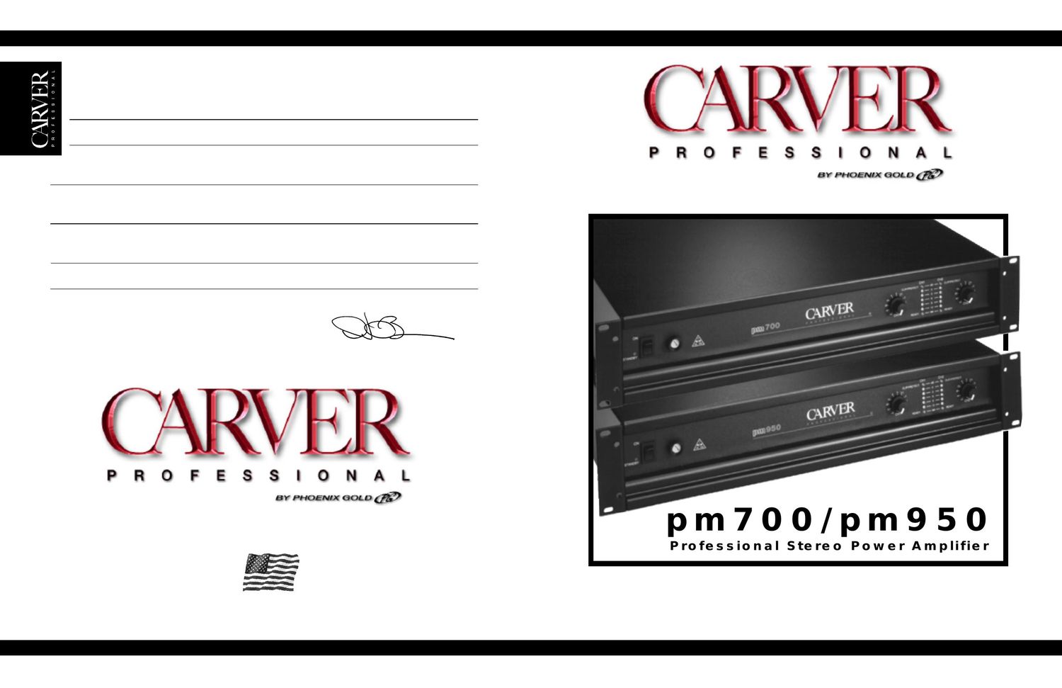
Carver PM 950 Owners Manual

This is the 20 pages manual for Carver PM 950 Owners Manual.
Read or download the pdf for free. If you want to contribute, please mail your pdfs to info@audioservicemanuals.com.

Page: 1 / 20
left right
Carver PM 950 Owners Manual

Extracted text from Carver PM 950 Owners Manual (Ocr-read)


Page 1

Introduction . . . . . . . . . . . . . . . . . . . . . . . . . .1 Unpacking and Paperwork . . . . . . . . . . . . . . .1 Features and Specifications pm700 . . . . . . . . . . . . . . . . . . . . . . . . . . . .2 pm950 . . . . . . . . . . . . . . . . . . . . . . . . . . . .4 Controls and Functions . . . . . . . . . . . . . . . . . .6 Installation Location and General Precautions . . . . . . . . . . . . . . . . . .8 Mechanical Considerations . . . . . . . . . . . . .8 Rear Support for Road Applications . . . . . . . . . . . . . . . . . . .8 Thermal Considerations . . . . . . . . . . . . . . .8 AC Power Considerations . . . . . . . . . . . . . .9 Magnetic Leakage Considerations . . . . . . . . . . . . . . . . . . . . . .9 Input W iring . . . . . . . . . . . . . . . . . . . . . . . .9 Input Sensitivity . . . . . . . . . . . . . . . . . . . . .9 Output W iring . . . . . . . . . . . . . . . . . . . . . .10 Installation (continued) Polarity . . . . . . . . . . . . . . . . . . . . . . . . . . .10Dual Mono . . . . . . . . . . . . . . . . . . . . . . . .10 Bridged Mono . . . . . . . . . . . . . . . . . . . . .10 Parallel Mono . . . . . . . . . . . . . . . . . . . . . .10 70V Distribution Systems . . . . . . . . . . . . .11 Clipping Eliminator . . . . . . . . . . . . . . . . . 11 Level Defeat . . . . . . . . . . . . . . . . . . . . . . . 11 Power ON Sequencing . . . . . . . . . . . . . . .11 Remote Turn-On of One or More Amplifiers . . . . . . . . . . . . . .12 Operating Tips Using the pm700/pm950 . . . . . . . . . . . . . .13 Accessory Options . . . . . . . . . . . . . . . . . .13 Servicing Instructions . . . . . . . . . . . . . . . . . .14 In Case of Difficulty . . . . . . . . . . . . . . . . . . .15 Care and Service Assistance . . . . . . . . . . . . .16 W arranty Information . . . . . . . . . . . . . . . . . .17 Table Of Contents CAUTION RISK OF ELECTRIC SHOCK DO NOT OPEN CAUTION: TO REDUCE THE RISK OF ELECTRIC SHOCK DO NOT REMOVE COVER (OR BACK) NO USER-SERVICEABLE PARTS INSIDE REFER SERVICING TO QUALIFIED SERVICE PERSONNEL The lightning flash with arrowhead symbol within an equilateral triangle is intended to alert the user to the presence of uninsulated "dangerous voltage" within the product's enclosure, that may be of sufficient magnitude to constitute a risk of electric shock to persons. The exclamation point within an equilateral triangle is intended to alert the user of the presence of important operating and main- tenance (servicing) instructions in the literature accompanying the appliance. Safety Information

Page 2

Introduction Congratulations on your purchase of a new Carver Professional Power Ampl\ ifier. It is backed by state-of-the-art engineering and manufacturing techniques to bring you the best in quality craftsmanship and reliable performance. The pm700 and pm950 are speciall\ y designed for pro sound applications. Their rugged construction and low profile make them \ ideal for sustaining the abuses of the road with reliability and space-saving economy. And their accurate sound and ample power make them ideal for critical studio applications as well. The pm70\ 0 is rated at 350 watts perchannel into 4 ohms and 225 watts per channel into 8 ohms. In bridged mo\ no operation it is rated at 700 watts into 8 ohms. The pm950 is rated at 475 watts per channel into 4 ohms and 325 watts per channel into 8 ohms. In bridged mono operation it is rated at 950 watts \ into 8 ohms. The sophisticated protection circuits designed into these amplifiers will protect your sys\ tem should an unexpected fault occur. They also protect the amplifiers from excessive temperature, continuous current limiting and shorted outputs. The balanced input uses a high quality, high common-mode reject\ ion differential amplifier for excep- tional hum and noise rejection. The sequencing feature allows a rack of \ amplifiers to be powered up from a remote location. The daisy-chain connection scheme causes each amplifier\ to turn on in sequence, preventing the l a rge in-rush current that can occur when an entire rack of amplifiers is turned on s i m u l t a n e o u s l y . These power amplifiers were designed and manufactured by people with a lifetime commitment to providing the worlds finest components for music and s\ ound reproduction. Thanks for placing your confidence in Carver Professional. We know your amplifier will provide many years of dependable s e r v i c e and reliable sound reproduction. Unpacking and P aperwork Carefully unpack the amplifier and keep the original carton and packing \ materials for future moving, shipment or long-term storage. After opening the box, please check for a\ ny visible signs of damage that were not apparent from the outside of the box. If you do encounter what appea\ rs to be concealed damage, please con- sult your Carver Professional Dealer before installing the unit. Important Paperwork Make sure to save your sales receipt. Your receipt is extremely important to establish the duration of your Limited W arranty, and for insurance purposes. Next, make a note of the serial num\ ber which is located on the back of the amplifier. Record it in the space provided below for conveni\ ent reference. Model: pm700 pm950Serial Number: Purchased at: Date: F i n a l l y , take a moment to fill out and return the Warranty Registration Card pa\ cked with the amplifier and return it to Carver Professional. This will allow us to keep you informed about\ new products as they become available. 1

Page 17

Power On, Low Output or No Output Low or no output problems are usually signal-source, bad cable or partia\ l output short circuit related. If the items listed below check out, then the problem may be internal to the pm700 /pm950. 1. The Input Level controls are set too low. 2. Move the input connections to another amplifier that you know is working\ to verify that it is not a source problem. 3. Check the speaker connections. Be sure that there are no small strands o\ f wire touching similar strands coming from the other wire in the cable. 4. Make sure the speakers are functioning correctly. 5. If you are using bridged-mono mode, ensure that the Stereo/Mono switch i\ s set correctly. 6. Use a voltmeter to determine if the power line voltage is dropping exces\ sively when the amplifier is driven hard. Playback Is Mixed with Hum 1. Check or replace the connecting cables. 2. Make sure that each screw terminal connection is tight. 3. Signal cables may have been routed too closely to AC cables, power trans\ formers, motors or other EMI inducing device. 4. T ry connecting another source to the power amplifier inputs. If the hum s\ tops, the problem lies with the original source component. Distortion Distortion is usually caused by excessive loss in the input controls (t\ he mixer/equalizer/crossover cant produce enough output), overdriving resulting in output clipping, or current limiting caused by \ excessively low load impedances. 1. Check the setting of the Input Level controls. If set too low, the prece\ ding piece of equipment may not have sufficient output to overcome the loss. 2. Check the speaker connections and verify that all screw connections are \ tight and that there are no stray strands of wire to cause short circuits. 3 . Verify that the total load impedance presented to the amplifier is withi\ n the limits described in this manual for the mode of operation selected. Care and Service Assist ance C a re: Wipe off the pm700 /p m 9 5 0 s front panel and chassis from time to time with a soft, dry cloth. If y\ ou have something stubborn to remove, use a mild dish soap or detergent sparingly applied to a soft\ cloth. Dont use alcohol, ammonia, or other strong solvents. Service Assistance: We suggest that you read the Limited Warranty completely to fully unders\ tand your warranty/service coverage. Please promptly complete and return the Warranty Registration Card. Also\ be sure to save the sales receipt in a safe place. It will be necessary for warranty service. If your CARVER Professional product shou\ ld require service, you may contact the CAR V E R Professional Technical Service Department by calling (503) 288-2008 or\ by writing to us at the Factory address shown below. We will then direct you to the nearest in our national network of Authorize\ d Warranty Service Centers or give you detailed instructions on how to return the product to us for prompt action. If you should have\ questions or comments, please write to the Factory address given below. Please include the model and serial number of your Carver P\ rofessional product, your complete address and a daytime phone number. Carver ProfessionalService DepartmentP .O Box 83189 Portland, OR 97283 Phone (503) 978-8510 - Fax (503) 978-3302 Carver Professional reserves the right to improve its products at any ti\ me. Therefore, specifications are subject to change without notice. 16