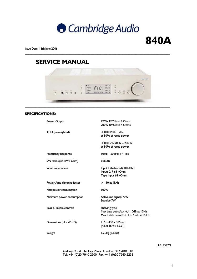
Cambridgeaudio 840A int sm

This is the 63 pages manual for cambridgeaudio 840A int sm.
Read or download the pdf for free. If you want to contribute, please mail your pdfs to info@audioservicemanuals.com.

Page: 1 / 63
left right
cambridgeaudio 840A int sm

Extracted text from cambridgeaudio 840A int sm (Ocr-read)


Page 1

840A SERVICE MANUAL TABLE OF CONTENTS Safety Precautions & Important Notes 4 Block Diagram 5 Exploded Diagram 6 Exploded Diagram Parts List 7 Front Panel PCB Schematic (Microcontroller & LCD) 8 Front Panel PCB Schematic (Shift Registers) 9 Front Panel PCB Layout (Top Side) 10 Front Panel PCB Layout (Bottom Side) 11 Front Panel PCB BOM 12 Input PCB Schematic (Input Select) 13 Input PCB Schematic (Input Control) 14 Input PCB Schematic (Input Amplifier) 15 Input PCB Board Layout (Top Side) 16 Input PCB Board Layout (Bottom Side) 17 Input PCB BOM 18 Preamp PCB Schematic (Relay Logic) 19 Preamp PCB Schematic (Tone Control) 20 Preamp PCB Schematic (Post Amp) 21 Preamp PCB Board Layout (Top Side) 22 Preamp PCB Board Layout (Bottom Side) 23 Preamp PCB BOM 24-25 Power Amplifier Schematic (Right Power Supplies & PSU) 26 Power Amplifier Schematic (Right Channel) 27 Power Amp Right & PSU PCB Board Layout (Top Side) 28 Power Amp Right & PSU PCB Board Layout (Bottom Side) 29 Power Amp Right PCB BOM 30-31 Power Amp PSU PCB BOM 32 Power Amp Schematic (Left Channel) 33 Power Amp Schematic (Left Power Supplies) 34 Power Amp PCB Board Layout (Top Side) 35 Power Amp PCB Board Layout (Bottom Side) 36 Power Amp Left PCB BOM 37-38 Hub PCB Schematic 39 2

Page 2

Hub PCB Board Layout (Top Side) 40 Hub PCB Board Layout (Bottom Side) 41 Hub PCB BOM 42-43 Rectifier PCB Schematic 44 Rectifier PCB Board Layout (Top Side) 45 Rectifier PCB Board Layout (Bottom Side) 46 Rectifier PCB BOM 47 IC Pin Layout Details 48-49 Technical Description 51-60 Procedure to upgrade the Control (Pic) Software 61-62 Notes 63 3