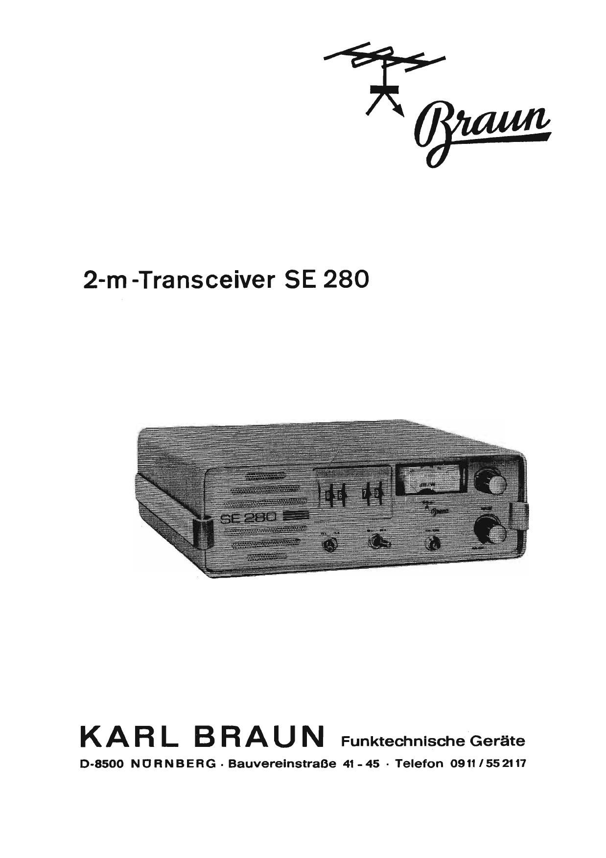
Braun SE 280 Service Manual

This is the 39 pages manual for Braun SE 280 Service Manual.
Read or download the pdf for free. If you want to contribute, please mail your pdfs to info@audioservicemanuals.com.

Page: 1 / 39
left right
Braun SE 280 Service Manual

Extracted text from Braun SE 280 Service Manual (Ocr-read)


Page 1

2-m-Transceiver SE 280

KA R L B R A U N Funktechnische'Geréite

D-8500 N U H N B E R G - Bauverelnstraee 41 - 45 - Telefon 0911 / 55 2117

Page 2

Lieber 0M!

Nun steht l H R SE 280 vor lhnen.

Wir haben dieses Gerat ohne Kompromlsse
konstruiert. Ohne Kompromisse im Aufwand
der Bauteile, ohne Kompromisse in der
Qualitat der verwendeten Bauteile. Alles,
was-Sie von einem modernen FM Kanalgerat
erwarten, ist vorhanden. Ohne Racksicht
auf den hohen Aufwand und den damit ver-
bundenen Preis.

Der SE 280 ist heute so durchkonstruiert,
daft es keine wesentliche Anderung mehr
geben wird. Der SE 280 ist durch seine
Konzeption absolut zukunftsicher und Sie
werden sich nicht mehr érgern mUssen, wenn
aus irgendelnem mehr oder weniger sinn-
vollen Grund, erneut die Relais- bzw.
Kanalfrequenzen geéndert werden. lhr SE 280
wird solange es Kanal- und Relaisbetrieb
gibt, "up to date" und "Spitze" bleiben und
deshalb seinen hohen Marktwert behalten.

Sie besitzen jetzt ein Geri-it, das a I I e n
Anforderungen des 2-m FM-Betriebes gerecht
wird. Trotz der Ubersichtlichen Gliederung
der Frontplatte sollten Sie die Beschreibung
des SE 280 ausfflhrlich studieren, damit Sie
auch alle M'dglichkeiten, die lhnen dieses
Gerat bietet, voll nutzen konnen.

Schon nach kurzer Zeit werden Sie fest-
stellen, was Sie mit dem SE 280 alles an-
fangen k'onnen. Sie werden staunen, wieviele
Stationen auch auBerhalb derfiblichen Quarz-
kanale qrv sind. Sie werden viele OMs
finden, die auch einen SE 280 oder ein
durchstimmbares Geréit' besitzen und mit
denen Sie sich auf jedem beliebigen Kanal
unterhalten konnen solange Sie wollen, ohne
dabei ein Relais zu blockieren. Sie werden
sich freuen, daB Sie Liberall wo immer Sie
auch hinkommen, einsteigen konnen. Kurz
gesagt, Sie werden mit den vielen OMs, die
schon einen SE 280 besitzen der Meinung
sein, daB der SE 280 wirklich seinen Preis
wert ist.

Viel Freude, viel SpaB und viel Erfolg mit
lhr-em SE 280 wflnscht lhnen

lhr DJ 3 DT

Dear OM,

You are now in possession of your SE 280.

We have constructed this transceiver with-
out any compromises with respect to the
number and cost of components, and without
any compromises as to the quality of the
components used. The SE 280 transceiver
is constructed to full professional standards
and offers you everything that one can expect
from a PM fixed-channel transceiver. The
motto of our company is "quality first" which
we place more importance to than low-cost.

The state-of-the-art used in the SE 280 is
so modern that no improvements in the tech-
nical standard can be expected for ._a con-
siderable time, especially with respect to
amateur radio equipment. The SE 280 is
really state-of-the-art and the owner will
never be upset by changes in the repeater
and channel frequencies and having to pur-
chase new crystals. As long as FM activity,
repeater and fixed channel operation is
present, the SE 280 will provide you with
the most up-to-date and leading transceiver
on the market, and will retain its value for
years and years to come.

You now possess a transceiver that satis-
fies all demands placed on 2 n1 FM equip-
ment. In spite of the clear layout and mark-
ings on the front panel of the SE 280' it is
adviseable for you to read through this
handbook so that you can use all facilities
provided by the transceiver to the full.

You will soon discover the versatility of the
SE 280 in comparison with other crystal
controlled FM transceivers and be surprised
at the number of other stations that can be
worked off the standard repeaters and calling
frequencies. You will be able to contact
other stations also using a SE 250 or VFO-
controlled equipment. Remember that the
SE 280 uses the 25 kHz spacing laid down
for FMtransmissions in Europe by the IARU.

The SE 280 allows you to be immediately
ready for operation on any of the 80 FM
channels laid down for FM operation. It is
ready for immediate operation via any of the
repeaters in operation or planned in the
whole of Europe. it is only necessary to
calculate the cost of purchasing crystals
for just 10 channels in order to see why
the SE 280 is really value for money.

We would like to wish you lots of pleasure
and success with your SE 280

Yours DJ 3 DT

Page 19

4.5

C150

Hub:

Sollte die Einstellung des Hubes nach
3.9 nicht moglich sein, oder soll ein
vorhandenes, aber unempfindliches Mi-
krofon verwendet werden, kann die
Mikrofon-Verst'airkung ethSht werden.
Zu diesem Zweck wird ein 10-22 PF/
3v Elektrolytkondensator(C166, Bild 5)
in den NF-Vorverstfirker eingelotet.
Die erforderlichen Leiterplatten-Boh-
rungen sind vorhanden.
Mikrofon-Verstéirkung und Hub sind
nach 3.9 neu einzustellen.

Ton ruf-Hub:

Unabhfingig von der Einstellung des
Sprachhubes (3, 9) kann n a c h Ein-
stellung des Hubreglers der Tonrufhub
mittels R 114 (an L6tstiften, Bild 5)
verandert werden. Soll der Tonrufhub
grtiBer werden, ist R 114 zu vergrds-
sern, bzw. umgekehrt.

M12

124

120

151

C 140

C 136

Deviation:

If it is not possible to adjust the fre-
quency deviation as given in section
3.9, or if an insensitive micrOphone
is to be used, it will be necessary to
increase the gain of the audio amplifier:
This is made by soldering a 10-22 PF/
3V electrolytic capacitor into the AF-
preamplifier (C 166, see Fig. 5). The
required holes are already provided
on the PC-board.

Realign the microphone gain and devi-
ation as given in 3. 9.

Deviation of the calling tone:

The frequency deviation of the calling
tone can be adjusted independently of
the Voice deviation by changing of R 114
(at the connection pins shown in Fig. 5).
The resistance value should be in-
creased to increase the deviation,and
VIce-versa.

M11

C 128

C 132
C 102
C 106
C 109

L17
R93
L18

Bild 6 - Figure 6 19

Page 29

1.

2.

Empfanger HF-Tei l:

Panorama-Empfanger an M 9
(eehause von T 10, Bild a).

Empféinger-Kanalschalter auf Kanal
40 schalten.

L 9 auf gr'oBte 134,3 MHz-Marken-
amplitude am Panorama-Empféinger
abgleichen.

Wobbler mit 145, O MHz-Mittenfre-
quenz an Antennenbuchse (BuZ).

134 MHz-lnjektion direkt amEmp~
fangerbaustein Punkt I nach Masse
kurzschliefien.

NF-Eingang Von Wobbler an M 9
(Gehéluse von T 10).

L 6, L 7, L 8 auf symmetrische
DurchlafSkurve (ohne Einsaltelung)
abgleichen.

5. 7 Empffinger ZF-Teil:

1. Meflsender mit ca. 0,4 1.1V bei 145,0
MHz an Antennenbuchse (BuZ), 3kHz
Hub.

2. L 4 (Bild 6) auf S-Meter Maximum
abgleichen.

3. L 5 auF bestes Signal/Rauschver-
haltnls abgleichen.

4-. Ausgangsspannung des MeBsenders
auf ca. 25 PV erhiShen.

5. S-Meter mit R 86 auf 50 dB An-
zeige einstellen (siehe auch 4.6).

5.5 Sender:

1. 15W /60 Ohm VHF-Leistungsmesser
an Antennenbuchse (Bu2).

2. Panorama - Empféinger fiber Damp-
fungsglied oder Strahlungskopplung
an Leistungsmesser.

3. Sender-Kanalschalter auf Kanal 40
schalten.

1:. Mit c 106, C 102, c 128, c 132,

30

c 136, C 140 (Bild 6) auf grofite
145 MHz-Markenamplitude am Pano-
rama-Empfa'nger abgleichen.
Dieser Abgleich sollte nur bei ca.
2/3 der- maximalen Ausgangsleistung
vorgenommen werden. Dazu muB die
Ansteuerung durch Verstimmen von
L 18 nach und nach zurfickgenommen
werden.

L 17 is! fest abgeglichen undbraucht
in keinem Fall ver'éndert werden.

1.

2.

1.

Receiver RF section:

Panoramic receiver to testpoint M 9
(case of T 10, Fig. 6).

Switch the receive channel selector
to channel 40.

Align L 9 for largest amplitude of
the 134. 3 MHz marker on the pano-
ramic receiver.

Sweep frequency generator with a
center frequency of 145.0 MHz to
the antenna socket.

Short circuit the 134 MHz local
oscillator signal to ground at point
"I" of the receiver module.

AF-lnput of the sweep generator to
testpoint M 9 (case of T 10).

Align L 6, L 7, and L 8 for asym-
metric passband curve without dip.

Receiver lF section:

Signal generator having an output
voltage of approx. 0.4 11V at 145.0
MHz to the antenna socket; frequency
deviation 3 kHz.

Align L 4 (see Fig.6) for maximum
S-meter reading.

Align L 5 for best signal-to-ncise
ratio.

Increase the output voltage of the
signal generator to approx. 25 1.1V.

Adjust the S-meter reading with
R as to 50 dB (see section 4.6).

5. B Transmitter:

1.

15 W/60 Ohm VHF output power
meter to the antenna socket.

Panoramic receiver via an attenuator-
or loose coupling to the power meter.

Switch the transmit channel selector
to channel 40.

Align c 106, c 102, c 128, c 132,
C 136, C 140 (seeFig. 6) for largest
amplitude of the 145 MHz marker on
the panoramic receiver. This align-
ment should only be made at appro-
ximately 2/3 of the output power.
It is therefore necessary for the
drive to be reduced by detuning
L 18. L 17 is fixed and should not
be altered.