Braun Regie 520 Schematic

This is the 6 pages manual for Braun Regie 520 Schematic.
Read or download the pdf for free. If you want to contribute, please mail your pdfs to info@audioservicemanuals.com.

Page: 1 / 6
left right
Braun Regie 520 Schematic

Extracted text from Braun Regie 520 Schematic (Ocr-read)


Page 1

r34 4--->t


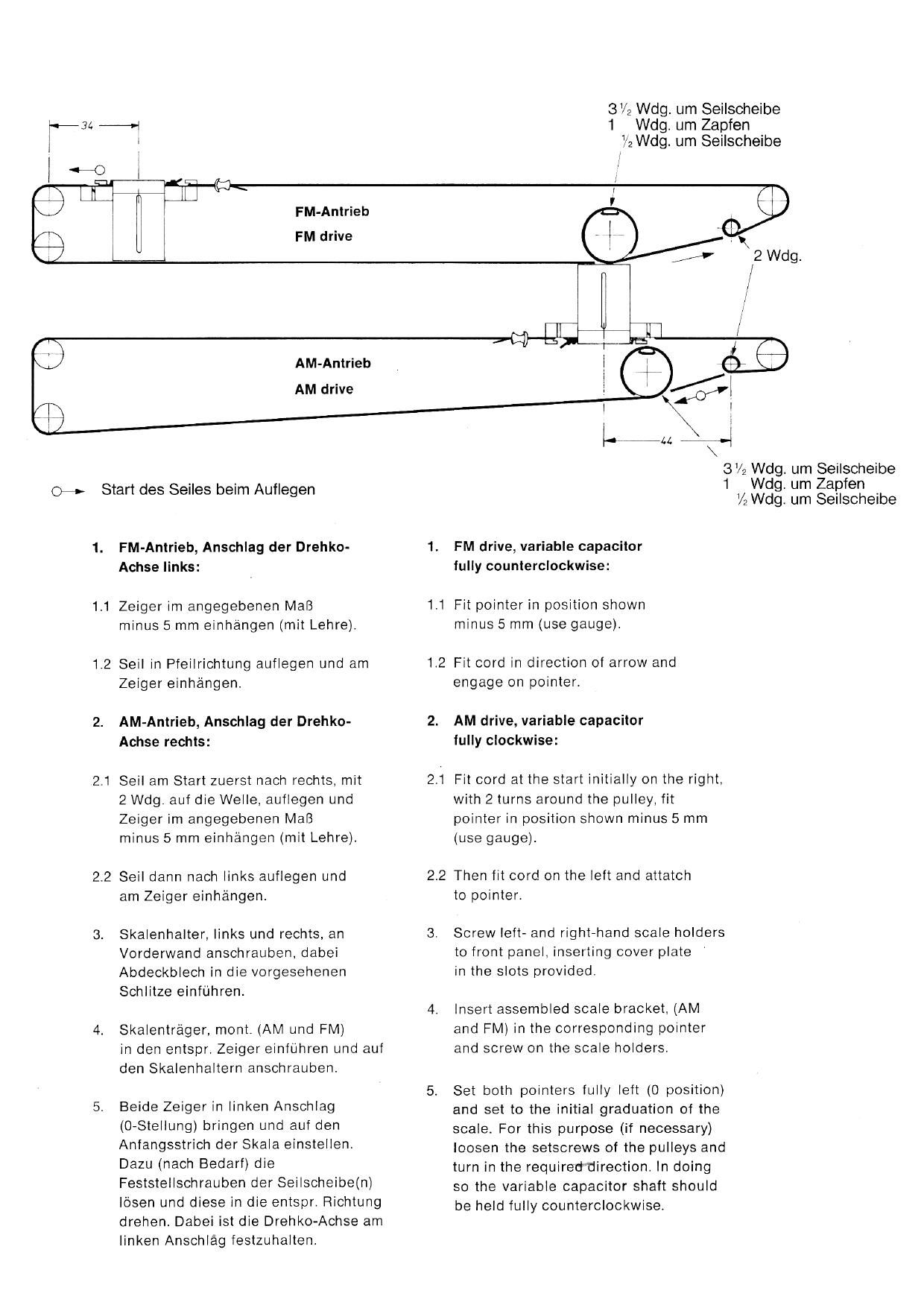
FM-Antrieb
FM drive

AM-Antrieb
AM drive

0-» Start des Seiles beim Auflegen

1. FM-Antrieb, Anschlag der Drehko- 1.
Achse links:
1.1 Zeiger lm angegebenen Mali 1.1

minus 5 mm elnhangen (mlt Lehre).

12 Sell in Pfeilrichtung autlegen und am 1.2

Zeiger einhangen.

2. AM-Antrieb, Anschlag der Drehko- 2.
Achse rechts:

2.1 Sell am Start zuerst nach rechts, mit 2.1

2 de. auf die Welle, auflegen und

Zelger im angegebenen Mali

minus 5 mm einhangen (mit Lehre).

2.2

22 Sell dann nach links auflegen und

am Zelger einhangen.

3. Skalenhalter, links und rechts, an 3,
Vorderwand anschrauben. dabei
Abdeckblech ln die vorgesehenen
Schlitze einfuhren.

4.
4. Skalentrager, mont. (AM und FM)
in den entspr. Zeiger einfu'hren und auf
den Skalenhaltern anschrauben.
5.

5. Beide Zeiger in linken Anschlag
(O-Stellung) bringen und auf den
Anfangsstrich der Skala einstellen.
Dazu (nach Bedarf) die
Feststellschrauben der Seilscheibe(n)
losen und diese in die entspr. Richtung
drehen. Dabei ist die Drehko-Achse am
linken Anschlag festzuhalten.

3V2 de. um Seilscheibe
1 de. um Zapfen
V2 de. um Seilschelbe

l/

3% de. um Sellscheibe
1 de. um Zapten
4de. um Seilscheibe

FM drive, variable capacitor
fully counterclockwise:

Fit pointer in position shown
minus 5 mm (use gauge).

Fit cord in direction of arrow and
engage on pointer.

AM drive, variable capacitor
fully clockwise:

Fit cord at the start initially on the right,
with 2 turns around the pulley, fit
pointer in positlon shown minus 5 mm
(use gauge).

Then fit cord on the left and attatch
to polnter.

Screw left- and right-hand scale holders
to front panel, inserting cover plate
in the slots provided.

lnsert assembled scale bracket, (AM
and FM) in the corresponding pointer
and screw on the scale holders.

Set both pointers fully left (0 position)
and set to the initial graduation of the
scale. For this purpose (if necessary)
loosen the setsorews of the pulleys and
turn in the requireddireotion. in doing
so the varlable capacitor shaft should
be held fully counterclockwlse.