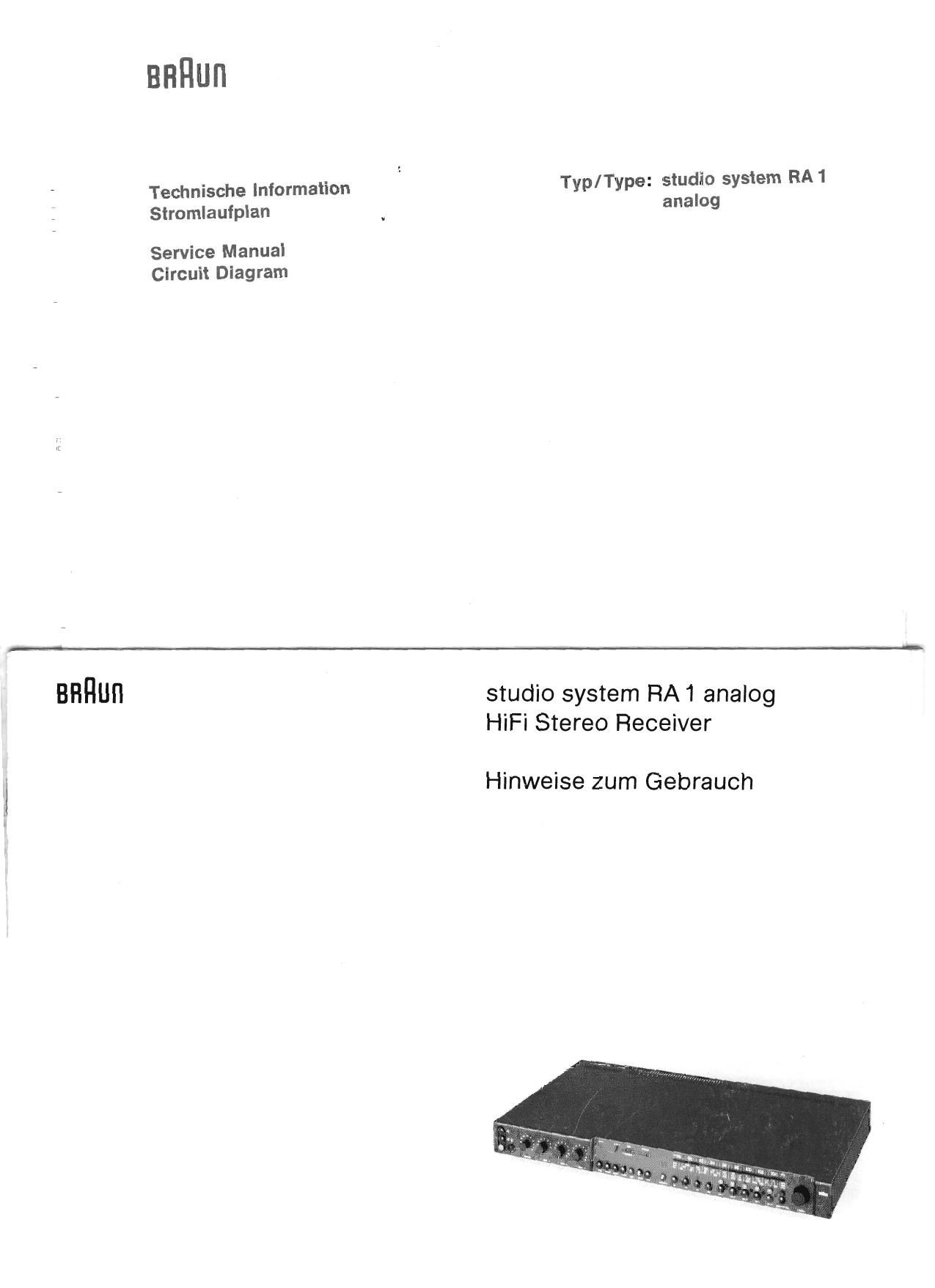
Braun RA 1 Service Manual 2

This is the 10 pages manual for Braun RA 1 Service Manual 2.
Read or download the pdf for free. If you want to contribute, please mail your pdfs to info@audioservicemanuals.com.

Page: 1 / 10
left right
Braun RA 1 Service Manual 2

Extracted text from Braun RA 1 Service Manual 2 (Ocr-read)


Page 7

Hinweise zum Stromlautplan
RA 1

Gezelchnete Schalterstellungen:

Stationstasten- nichl geclruckt
NF-Tasten: radio gedruth
Lautsprecher Lautsprecher 1
Tasten: gedruokt

Die im Endversta'rker angegebenen
Spannungswerte ohne Klammer sind mit
Nennleistung. jene mit runder Klammer sind
ohne Signal gemessen. Mittels Rechteck
eingerahmte Spannungswerte sind NFV
Spanriungen (Effektivwert).

Spannungsangaben ohne Bezugslinie sind
gegen Masse zu messen. Gemessen wird
generell bei 220 V Netzspannung und mit
einem MeBinstrument, dessen EingangsV
widerstand mindestens 50 kQ/V betragt,

Frequenzbereiche:

UKW 87,5... iO4MHz FMIZF: 10.7MHz
KW 5,8... 8,2MHz AMIZF2455 kHz
MW515 -1640 kHz

LW 145 .. 350 kHz

Oszillatorspannungen
UKW 60 mv L-Seite am EmitterT 103 }

KW
M W
LW

Met}-
punkt 2

Mali»
punkt 4

40...100 mV am Emitter T 202
100. .. 120 mV am Emitter T 202
130,..150 mV am Emitter T 202

gemessen mit UHF-Millivoltmeter URV
Rhoda & Schwarz.

Notes on Circuit Diagram
RA 1

Switches are shown in the following
positions:

Station push buttons: not depressed
AF push buttons: radio depressed

Speaker 1
depressed

Speaker push
buttons:

Voltages as indicated in the output stage not
in parentheses are measured with nominal
power and those in parentheses are measured
without signal. Voltages in square parentheses
are AF voltages (effective value).

Voltages without reference lines are
measured to ground (chassis). Measurments
should always be carried out at 220 V mains
voltage with a 50 ktl/V meter.

Tuning range:

UKW 87.5 104 MHZ FM/lF 10,7MHZ
KW 5,8... 8,2 MHZ AM/ lF:455 kHz
MW 515 . lfi40 kHz
LW 145 . 350 kHz

Local oscillator voltages:

\ _ 1 test
UKW 60 ml L-Side at emitter T 108 1 point 2
KW 40...100 mV at emitter T 202 test
MW 100.,.120 mV at emitter T 202 pomt 4

LW 130 , . . tSO mV at emitter T 202

measured with Rhode & Schwarz UHF
Millivoltmeter, type URV.