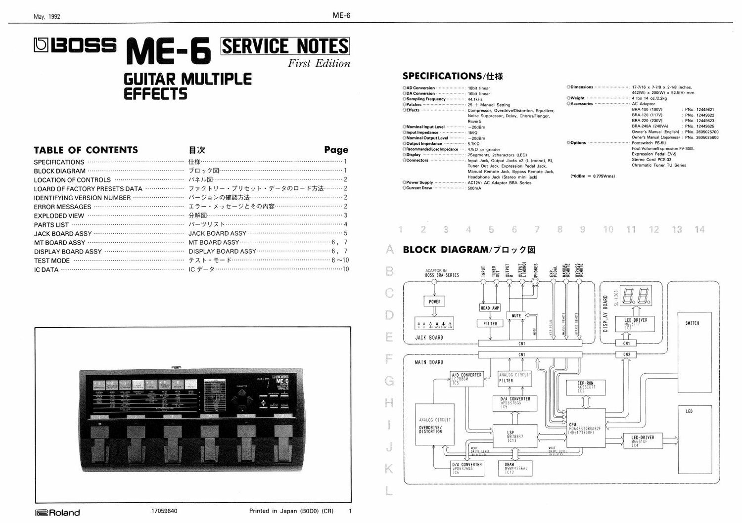
Boss ME 6 Multi Effects Service Manual

This is the 12 pages manual for Boss ME 6 Multi Effects Service Manual.
Read or download the pdf for free. If you want to contribute, please mail your pdfs to info@audioservicemanuals.com.

Page: 1 / 12
left right
Boss ME 6 Multi Effects Service Manual

Extracted text from Boss ME 6 Multi Effects Service Manual (Ocr-read)


Page 1

May, 1992

RAE-6

@3055 ME-

SERVICE NOTES

F z'rst Edition

GUITAR MULTIPLE

EFFECTS

TABLE OF CONTENTS

E )3! Page

SPECIFICATIONS ............................................... 1i$¥ .................................................................... l

BLOCK D|AGRAM ...............................................
LOCATION OF CONTROLS ------------
LOARD OF FACTORY PRESETS DATA ------------------
IDENTIFYING VERSION NUMBER ------------------------
ERROR MESSAGES ----------------
EXPLODED VIEW
PARTS LIST .................
JACK BOARD ASSY ..........................................
MT BOARD ASSY ----------
DISPLAY BOARD ASSY

TEST MODE .................
1c DATA ............................................................

7Dv7l


[Tin/.-

777 w- - 7"Ut~y h'?--$10)CI-- Ffii
N73/®I§§E?§T§E ............................................ 2
15* - xyt-yticwmgrAr --2
mal- ~3
IT-y U1 l~u~

JACK BOARD ASSY .............................................. 5
MT BOARD ASSY ----------- -~6, 7
DISPLAY BOARD ASSY 6, 7
511 |\ . f- I: ................................................ 8~I0
IC 72_g .............................................................. 10

@Roland 17059540

Printed in Japan (BODO) (CR) 1

SPECIFICATIONS/111$

@AD Conversion 18bit linear
(EDA Conversion TGbIt linear

(@Sampling Frequency
©Palches --
(QWBDTS

44.1kHz
25 + Manual Setting

@Dimensinns ------------ v ----- 1777/16 x 7v7/8 x 2-1/8 inches.

442(W) x ZOOIW) x 52.504) mrn
©W-|ght -- - 4 lbs 14 onZZkg
©Accessaries

~ Compressor, Overdrive/Distomon, Equalizer,

Noise Suppressor, Delay. Chorus/Hanger,

Reverb


@Nominnl Inpu LBVeI *ZOdEm
©Input Impedance 44444 7M 0
@Nominnl Output Level ~ *20dEm
©0utput Impedance " 5.7K0

©Recammended Load lmpedlnoe ~
©Displav ------
@Connmors

47m or greater
~ 7Segments, Zcharaczors (LED)

Tuner Out Jack, Expression Pedal Jack.

~ . AC Adaptor

@Options

~ Input Jack, Output Jacks x2 (L (mono), R),

Manual Remote Jack, Bypass Remote Jack.

Headphone Jack (Stereo mini jack}
~ AC12V: AC Adaptor BRA Series
' SOOmA

©Puwer Supply -
©Current Draw ~~

7;:
r
.

5.2

ADAPTOR W
8055 BRA-SERIES

INPUT
TUNER

IHEAD AMP

I
LflLELI

IIUTE

.4
<
2
no:
4
a

m mm

REMOTE
FA

("MBm = 0.775Vrms)

REMOTE

BRAJOO (TOOVI
BRAAIZO (I17V)
BRA-220 (230W
BRA-240A (240VAJ

Footswitch FS-SU

Foot Volume/Expression FV«300L

Expression PedaI EV-S
Stereo Cord FCS~33
Chromatic Tuner TU Series

: PNo.
: FNo.
: PNo.
: PND.
Owner's Manual (English) : PNo.
Owners Manna! (JapameseI : PM).

1 2449621
1 2449622
1 2449623
1 244962 5
2605025700
2605025500

DISPLAY BOARD

avms REMOTE

/

MAIN BOARD

ANALOG CIRCUITI
FILTER

I I
/A CONVERTER
EEGWBGS

an
a o
:2
<
m
:5
_.
m
x

D
u
I

/.__

wont
DRIVE LEVEL

RUM
DRIVE LEVEL
an n In

(I

Inwwn} I I

D/A CONVERTER ORAN A
$325376 MaggszEAJ
\, r

SL425?


QED
25E

I
I
I

SWITCH

LED

Page 2

ME-G

LOCATION OF CONTROLS/A? IDEEEE

Top Case
(2204038400)

LED (red) Panel 7369 LED (red)
GL5HD43 (2221096000) SL-1263 GL5HD43
(15039227) (15029551) (15039227)

Switch

SKHHBW

(13129774)

\ K F-I l

k\h\\

fi- - I
I \
Top View
LED (red)
SLP-1SSB-81
(15039220) NOTE : The buttons (used on ME-G) cannot supply as replacement parts separately
for ME-Gs mechanism. The replacement buttons are included in the "Top
. Case".
8 t h P d l .. , .. . .t ,, - .
(30; e a EzMEv6lilillfiliéhfme/t71ffili. fitifiimflmfu Top Case will/7L0;
(2218060500) are sex». 7R5? Vifili, Top Case" neehflitraehiao
Support Spring
#1103
(2217010300)
Rubber Foot #35
(********)
Pedal Switch
SKOJAE
(13129777)
Jack Jack
YKBZ1-5012 w/Sw YKBZ1-5010
(13449146) (13449145)
Cord Hook
(2236071200)
W a" a; w" :0 mam-x. r: : 2:5
; e 3 a}
o a .99, 0 00 e [(91%
Rear Side
Bottom Base Jack AC Jack Bottom Cover
#312 HSJ-0912-01-040 HEC0740~01-010 (2203040100)
(2235031200) (13449434) (13449728)

May, 1992

LOAD OF FACTORY PRESETS DATA/777 |~ U - - 7°Ut'7 |~ ' i-5W)EJ- F075;}

©CAUTlON !!
You cannot use an external sequencer to save the ME-6
user data via MlDl. This should be explained to the
customer who requested servicing.

1. Turn the power off
2. Press and hold the [PARAMETER V"] button and

[{"] button and turn the power on again.

3. The [EDIT/ESC} indicator will falsh and the display will
read ,_,:/

* To cancel the initialization at this time, press the
[EDIT/ESC] button. You will be returned to the Play
Mode.

4. Press the [WRITE] button.
5. When the initalization is complete,youll be moved to
the Play Mode.

@1150!
MBS (DJ-err"- - as 7 in 11M); 2 7 Vireo: MIDI
E1011] LClléfl'fé C. J: life I'd/0,. "Pbllééiillérliillfi
:5 7iL7;i5%¥iéfl:, %®fi%ifi_l%é Lf'lé Z) i 5 $5511be
10.,

1.72 EvifliLi'h

2, (PARAMMER [v], [4]] (+157 V rrrrlfifrlnrpug-firg.

1805i? ON L: L i To
3. [EDIT/ESC] i7) 4 y Wr~ 7 warm Lt. % r1 7
l/ i l: "I. 1:!" iii/112311;?)
* (JJZUIIKElJ.)IZ?LZ> & a 1:, [EDIT/ESC] 7&7 7 Mil
Lflew
MW? " ibxflfitlul 1:1);
4. [WRITE] $7 > Mil L it
5. 4210/07 rfiimlwte he an iillliiltfiiiiébé t.
imaoiainiitemta lul Elkfilie 1) i to

.172? if.»

IDENTIFYING VERSION NUMBER/Ii- / a 706E533}?

NOTE: For Ver, 1.00, the version number cannot be
identified.

1. While holding down [PARAMETER {>1} and [VALUE 1
A]] keys, turn on power.
The LED above one of pedals 1 to 5 and display will
show the current firmware version.
Example: LED above pedal No.1 lights and the
display reads 0 1. This means Ver. 1.01.

iii. Ver, 1.00 51:. 19 :23 703%? iyi6§ ifiho

1. ~11, 33:151.? OFF (:Li'ic
2. (PARAMETER [>1] rriswa [VALUE [A1] #157
A [EDlF/ESC] diswe, lrilfiri:lilll,0»7lieaaéee
()NilLiio
H-va yoga/51:7 1 (xi 7-H) LEDl-S 35.10;
[VALUE/BANK] 101.120 60 {fawn
tkili. Vcr. 101097») r24 v-rmmm
\ . L, [VALUE/BANK] (01.00 7;? 5'," t
hernia:

ERROR MESSAGES/15- - X yt-9t%®l93

if an error message regarding DSP test is displayed after
test No.3 and before test No.4, take the necessary
measure according to the cause described below.

Em)!
message Sym ptOlTl

Possible cause
E0 DSP cannot be - Solder bridge, improper
initialized. soldering at portion anywhere
between CPU and DSP
DSP and/or CPU defective
E1 DSP IRAM defective - DSP defective
- Solder bridge, improper
soldering around DSP
E2 DSP ERAM defective - Solder bridge, improper
soldering at portion anywhere
between DSP and DRAM
- DRAM defective

f1ififi$fib4NfifiiéfiK£L¢bhéDw
fxv7fmlfiwX7t~?t%mfimfift%fim
$flWfi,£&E®uowrmmLiro

jig; tens sit-era
E0 DSP an ; 9 2v 7 - CPU-DSP 111107131117 '7 «r,
r we ate/w $5111tlt2<£t.~,
~DSP WFEC
. CPU rifles
El DSP IRAM 1? - ~DSP WEI-:9
DSP (51370073151119 7 a.
teat-limes
E2 DSP ERAM 1% ~ - DSP-DRAM301511157 7%.
31" mlwllflirt.
- DRAM 710%,.»