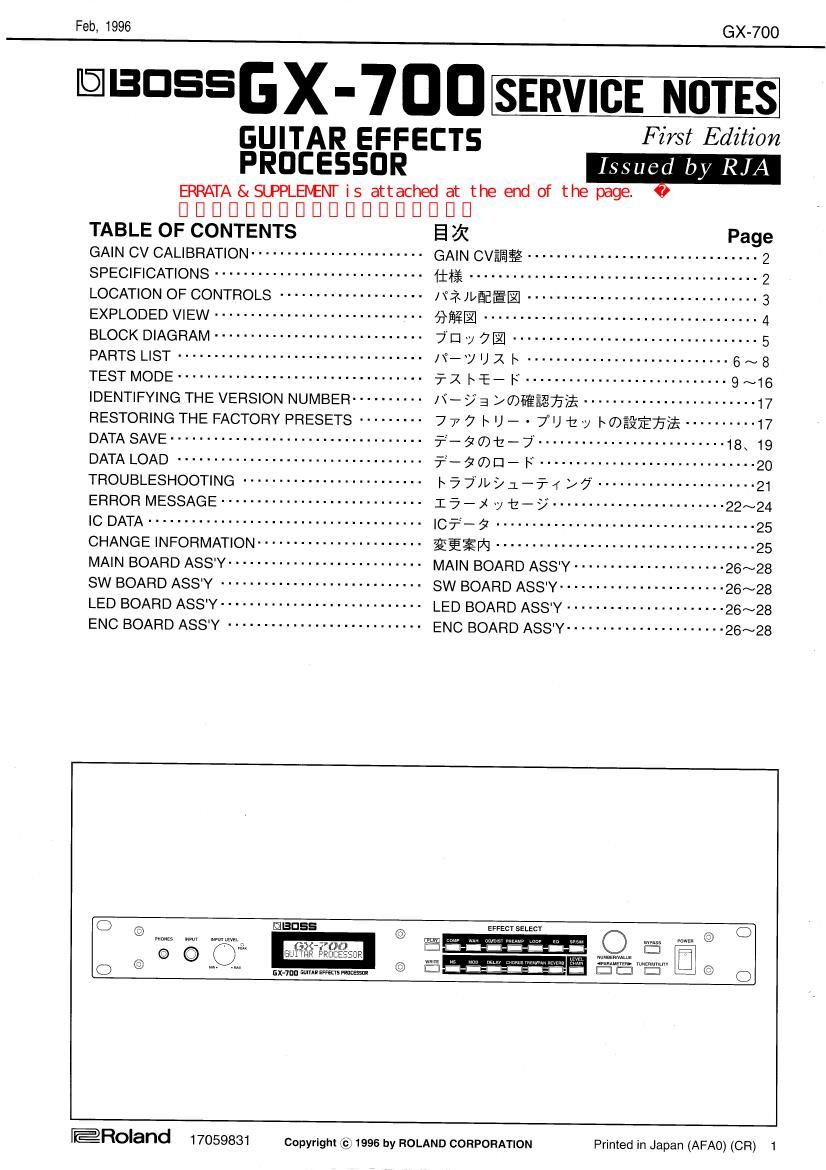
Boss GX 700 Guitar Effects Service Manual

This is the 29 pages manual for Boss GX 700 Guitar Effects Service Manual.
Read or download the pdf for free. If you want to contribute, please mail your pdfs to info@audioservicemanuals.com.

Page: 1 / 29
left right
Boss GX 700 Guitar Effects Service Manual

Extracted text from Boss GX 700 Guitar Effects Service Manual (Ocr-read)


Page 1

Feb, 1996 GX-700

DISHESGX-7IIIIII SERVICE NOTES
GUITAR EFFECTS First Edition

PROCESSOR W
ERRATA & SLPPLEBENT is attached at the end of the page.

DDDDDDDDDDDDDDDDDD

TABLE OF CONTENTS E 3i Page
GAIN CV CALIBRATION ........................ GAIN CVEEE ................................ 2
SPECIFICATIONS ............................. LEI; ........................................ 2
LOCATION OI: CONTROLS .................... [f2 gag. ................................ 3
EXPLODED VIEW ............................. Qfig- ...................................... 4
BLOCK DIAGRAM . . ........................ jEI y 7- .................................. 5
PARTS LIST .................................. /\°_y I) x I ............................ 6 ~ 8
TESTMODE .................................. 711 Lag-F ............................ 9~16
IDENTIFYING THE VERSION NUMBER ---------- N- > a >m-§£7aifi ------------------------ 17
RESTORING THE FACTORY PRESETS --------- 7 7 7 |~ U - - 7" U E y I waif/35$ ---------- 17
DATA SAVE ................................... 55-7012-7 .......................... 18 19
DATA LOAD .................................. 53-90EI- I: .............................. 20
TROUBLESHOOTING ......................... I\ 5 7", t/ :L _ 7-. f / 7 ..................... 21
ERROR MESSAGE ............................ I a _ j 7 t _ 3/ ...................... 22~24
IC DATA ...................................... I071:- 7 ................................. 25
CHANGE INFORMATION ....................... gfigw .................................... 25
MAIN BOARD ASS'Y ........................... MAIN BOARD ASS'Y ..................... 26~28
SW BOARD ASS'Y ............................ SW BOARD ASS'Y ....................... 26~28
LED BOARD ASS'Y ........................... LED BOARD ASS'Y ...................... 26~28
ENC BOARD ASS'Y ........................... ENC BOARD ASSY ...................... 26~28
Q @ mm WI nmuuu IEDSS © W EFFECTSELECY U W mm mm © C)
.8 E

@Roland 17059331 Copyright © 1996 by ROLAND CORPORATION Primed in Japan (AFAO) (CR) 1

Page 2

GX-700

© CAUTION
The GAIN CV calibration must be done before you give
back the unit to the user.

GAIN CV CALIBRATION/GAIN CVfifig
© NOTE
Keep the unit powered on several minites to warm it

before calibrating GAIN CV.

1.Turn the power back on while pushing [PREAMP] and
[SP.SIM] to enter the test mode.

2.Turn [NUMBER/VALUE] to select "9. GAIN CV"

Feb, 1996

© 323
:L-if- Iiiliillfl'élfifilllidzfGAIN Wilmette (T
em

((3 $23
GAIN cvamififi numeeeem tmjlwafiafi
tIMONLUamTTémO

%
%

1.[PREAMP] t [SP.SIM] Elfiflelflfiil/efiieeéifié
ONIZLCFX Id-:H Flamiao

. [NUMBER/VALUE] E IE] L T"9.GAIN CV" in??? L if
#0

3.Push [NUMBER/VALUE] to ca
automatically.

librate GAIN CV

[NUMBER/VALUE] MW .1: GAIN CVEEI¥ E a $1133
Ilfiw i to

=j_l
E

4.The result will be displayed after calibration.

.%E%fl§t%bé &*E%E§U-

SPECIFICATIONS/111%

CODA/D Conversion 22 bit AF Method
©D/A Conversion 8 bit 16 times Oversampling A 2 Modulation
©Sampling Frequency 4.1 kHz
©Program Memoryw 00: 100(User) + 100(Preset)
©Nominal Input Level : INPUT: -10 dBm RETURN: >10 dBm
©Input Impedance ----- : INPUT: 1 MD FIETURN: 450 kg
©Nominal Output Leve : OUTPUT: 710 dBm to + 4 dBm SEND: >10 dBm
©Output Impedance ~ OUTPUT: 3 k9 or less SEND: 2 k9
©Headphones Ou ut .2 mW (33 (1 Load)
©Dynamic 00 dB or greater (lHF-A)
©Controls -» .

INPUT LEVEL Knob, NUMBER/VALUE

WAH,OD/DIST, PREAMP, LOOP, EQ. SP.

Knob, POWER Switch. EFFECT PARAMETER Buttons(COMP.
SIM. NS. MOD. DELAY, CHORUS. TREM/PAN. REVERB, LEVEL

CHAIN) PLAY Button. WRITE Button. PARAMETER Button L/R, BYPASS Button, TUNER/UTILITY Button


OUTPUT LEVEL Knob
16 characters. 2 lines (backlit LCD)
EAK Indicator
:
INPUT Jack, HEADPHONES Jack

©Display ~
© Indicator
© Connectors

INPUT Jack, OUTPUT Jack L(MONO)/R, SEND Jack. RETURN Jack, Expression Pedal Jack. CONTROL 1/2
Jack, MIDI ConnectorsUN. OUT, THRU), AC ADAPTOR Jack

©Power Supply :AC 14V; Supply AC Adaptor
(BOSS BRO-100. 120. 230. 240)
©Current Draw : 800 mA

©Dimensions ~ 2482 (W) x 197 (D) x 44 (H) mm
19 (W) x 73/4 (D) x 1-3/4 (H) inches

(ElA-1U rack mount type)

©Weight~ ' .0 kg / 4 lbs 7 oz (excluding the AC Adaptor)
©Accessorles . Owners Manual Japanese (70674423)
English (70783823)
AC Adaptor BRO-100 (100V) (00899078)
BRO-120 (120V) (00899089)
BRO-230 (230V) (00899090)
BRO-240 (240V) (00899101)
©Options :MIDI FootController: FC-200(Roland), FC-50
Foot Switch: FS-SU, FS-5L
Expression Pedal: EV-5 (Roland).

FV-SOOL + PCS-33 (Roland)

' 0 dBm = 0.775 Vrms

2

Page 9

Feb, 1996

TEST MODE/5'1 l~ :E- F

CAUTION:
If the memory contains user data, be sure to save it to a
temporary memory device like a sequencer (MC-SOMKH
etc.) before performing repairs.
(To save the user data, refer to "DATA SAVE" and "DATA
LOAD".)

(3 Test items
1. Battery
2. LCD Contrast
3. LCD/LED
4. Key/Control
5. Expression Pedal
6. MIDI IN/OUT
7. DSP Check
8. D/A Test
9. Gain CV
10. OD/DS Mode
11. Noise(Output)
12. Noise(Send/Fteturn)
13. Noise(OD/DS)
14. Return
15. Frequency Response
16. Factory Load

© Required items
Foot SW(FS-5U x2)+Cable(PCS-31)
Expression Pedal(EV-5)
MIDI Cable
Noise Meter
Oscilloscope
Oscillator
Opened plug

C) To enter the test mode
Turn the power back on while pushing [PREAMP] and
[SP.S|M].

The display shows the version number.

GX-700

Sig:
:L-~f-0)7"-5775§}\9'CVZ2<;§13\figfiaéfififlfl
f-F-7E9-7>%~%(MC-50MKH%M:2M77v
7°Lusmro
(l-tf-?-7fi<%7fi£li." 7"'°-5W)t~7° 35:0
" rayon-F" EéfifiLTUfewo)

© 5- X l~ IE E

1. Battery
LCD Contrast
LCD/LED
Key/Control
Expression Pedal
MIDI IN/OUT
DSP Check
D/A Test
Gain CV
10. OD/DS Mode
11. Noise(0utput)
12. Noise(Send/Retum)
13. Noise(OD/DS)
14. Retum
15. Frequency Response
16. Factory Load

>0?°.\'.°\.V:>P!°

© J11 ET ;.5 4%
Foot SW(FS-5U x2)+f - 7°)l/(PCS-31)
Expression Pedal(EV-S)
MIDIT - 7*)1/
/ t 7: x - 5' -
tynzu-f
fifiefi
$7§7
© 5-K |~E- KMDJUUJ'
[PREAMP] a [SP.SIM] ix nae lzttti L am; 9 EU? EON
l: L i To

1t~§a Vfiififiéflifc

HUBE

.1.fi6

Turn [NUMBERNALUE] to select the desired test item
from among the following items. When the desired item
is displayed. Press [NUMBER/VALUE] to start the test.
Press [NUMBER/VALUE] again to exit from test of the
item.

[NUMBER/VALUE] 12 [iii L Ttfifi L f; WE a & iEJR L
s an [NUMBER/VALUE] MW t 7c®1E El otfiélx
Fink D i so Elf [NUMBER/VALUE] 754$? blag
lflfifixetfilriso