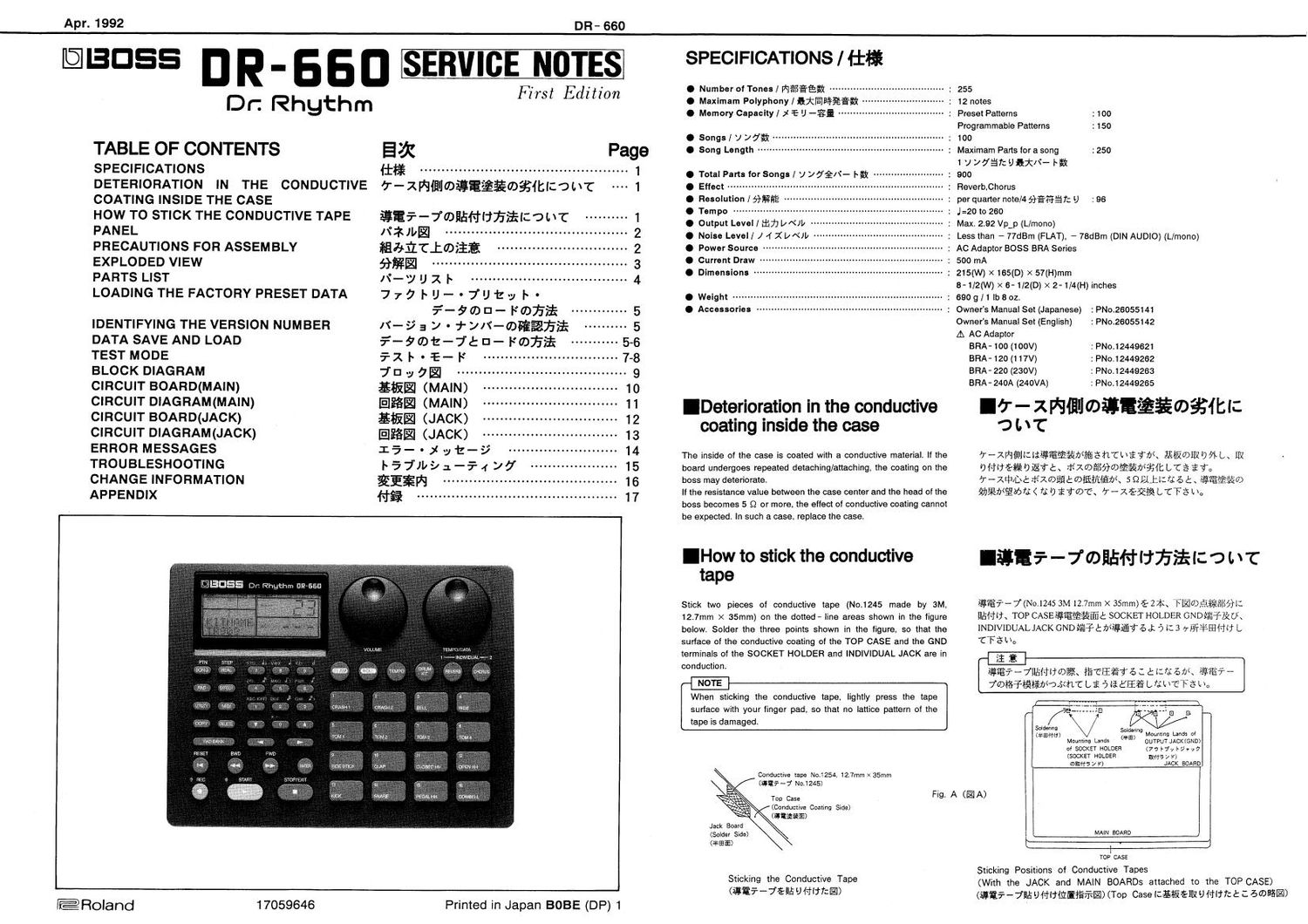
BOSS DR 660 SERVICE NOTES

This is the 17 pages manual for BOSS DR 660 SERVICE NOTES.
Read or download the pdf for free. If you want to contribute, please mail your pdfs to info@audioservicemanuals.com.

Page: 1 / 17
left right
BOSS DR 660 SERVICE NOTES

Extracted text from BOSS DR 660 SERVICE NOTES (Ocr-read)


Page 1

Apr. 1992

[@3055 D R - 6 5 D SERVICE NOTES

DR- 660

P7731 lfdition

Dr. Rhythm

TABLE OF CONTENTS

SPECIFICATIONS

DETERIORATION IN THE CONDUCTIVE
COATING INSIDE THE CASE

HOW TO STICK THE CONDUCTIVE TAPE
PANEL

PRECAUTIONS FOR ASSEMBLY
EXPLODED VIEW

PARTS LIST

LOADING THE FACTORY PRESET DATA

IDENTIFYING THE VERSION NUMBER
DATA SAVE AND LOAD
TEST MODE

BLOCK DIAGRAM
CIRCUIT BOARD(MAIN)
CIRCUIT DIAGRAM(MAIN)
CIRCUIT BOARD(JACK)
CIRCUIT DIAGRAM(JACK)
ERROR MESSAGES
TROUBLESHOOTING
CHANGE INFORMATION
APPENDIX

E&

Iifi ................................................ 1
7-2WfitmfiififioéfiltIzotxr 1
fiEi-Tmfififliifiifilzohc .......... 1
N3,- .......................................... 2
flafifioiifi .............................. 2
fifig ............................................. 3
,\°_\y [J X I .................................... 4

777IU-'7"JIZ-y I '
¥-90)D- F0323:-
m-yay-+yN-mmafifi
¥-9ot-7én-Pmfi$
5-1 I - =E- |~'
7'Ely7I
Evil (MAIN)
IEIESI (MAIN)
Evil (JACK)
IEIESI (JACK)

15"Xyt-9


F57lb91-5497 15
fiEfiW ..................... 16
fifi .............................................. 17

ems» i

VOLUMI

few-o

@Roland 17059646

Printed in Japan BOBE (DP) 1

SPECIFICATIONS / lifi

0 Number of Tones I Wefifiégg ...............
O Maximam Polyphony/fixfiafiggfi .
0 Memory Capacity/ x E I) --z§i ............

0 Songs/ 1 ydfi
0 Song Length ........

0 Total Parts for Songs] J ydg/t- |~§t
. Effect ......................
0 Resolution MM?
. Tempo ....................
0 Output Level l #117) UN» -
0 Noise Level/ J 4 Xt/Nllz
0 Power Source ------
0 Current Draw
0 Dimensions ------


0 Weight


IDeterioration in the conductive
coating inside the case

The inside of the case is coated with a conductive material. It the
board undergoes repeated detaching/attaching, the coating on the
boss may deteriorate

If the resistance value between the case center and the head of the
boss becomes 5 Q or more, the effect of conductive coating cannot
be expected, In such a case, replace the case.

IHow to stick the conductive
tape

Stick two pieces of conductive tape (Not1245 made by 3M.
12t7mm X 35mm) on the dotted- line areas shown in the figure
below, Solder the three points shown in the figure, so that the
surlace of the conductive coating ol the TOP CASE and the GND
terminals of the SOCKET HOLDER and INDIVIDUAL JACK are in

conduction

When sticking the conductive tape, lightly press the tape
surlace with your linger pad. so that no lattice pattern of the
tape is damaged

Cowductlve tape No.1254, 12.7mm x 35mm
(31!? - 7 M11245)

Too Case

(Conductive Coating Side)
(fili§fi)

Jack Board
(Solder Slde)
(fiififi)

Sticking the Conductive Tape
(iii-7555 U Hiifcl)

Fig A (IA)

" J 100

: 255
: 12 notes
.. : Preset Patterns : 100
Programmable Patterns : 150
.. : Maximam PaIts for a song : 250

1 JVO'EITCJIXN- by

: 900

: Reverb.Chorus

: per quarter note/4 game f: U : 96

I J=2O to 260

: Max. 2.92 Vp_p (L/mono)

: Less than - 77dBm (FLAT), - 78dBm (DIN AUDIO) (L/mono)
: AC Adaptor BOSS BRA Series

: 500 mA

: 215(W) >< 165(0) >< 57(H)mm

8-1/2(W)>< 6-1/2(D) >< 2-1/4(H) Inches

: 6909/1lbaozt
-- : Owners Manual Set (Japanese)

:PNO.26055141
Owners Manual Set (English) : PNo.26055142
A AC Adaptor
BRA- 100 (100V)
BRA-120 (117V)

BRA-220 (230V)

: PNO.12449621
: PNo.12449262
:PNO,12449263

BRA - 240A (240VA) : PNO.12449265
I6" - zfifliwigfifiofimz
O I. \ 'C

'7-maumeeeanwennewe ammo Lt mt
DHUE-fimzttt fixogfifimfifimafitbra are

'7 -meD& rrixofifitmfifiiE/fi 5 QLJJJZU a t ( fifififio
cheater)? 7; D iiwC-x r-xéafitfi! LTFS mo

lite-jmflfiflfifimour

§§?-7(N0,1245 3M 12.7mm x 35mm)$: Hit FIZIOJififieitéit:
warm TOP CAsEefifififit SOCKET HOLDER GNDfiHéLzm
INDIVIDUAL JACK GNDifi-Ftbiiéieaé at 5 I: 3 vfififiéflai'w L
'cTewu

it
SS? ~7alinzrcifit tafEETa : a at; 57»: ASE? -
joltsTtfiisttbsmc L, a 5 Ii Elie L nix-CT a L n,
"1 El B

V MW
(*3) Mounling Lands at

SOIGEIIHQ
(Ammo)
OUTPUT JACK (77 We ray-,7
lama 7 I')
JACK BOARD

Mountlnq Lands
ot SOCKET HOLDER
(SOCKET HOLDER

mums 7 F)

MAIN BOARD

TOP CASE
Sticking Positions of Conductive Tapes
(With the JACK and MAIN BOARDS attached to the TOP CASE)
(WIF- jflfiufilflfiitgffilfl) (Top Case Icélfiéfifl J (Tiff: 2: .2 6mi§®>

Page 2

DR- 660
PANEL/Nikit-

Display Cover DR- Knob L (BLK) DR- Knob L (BLK)
(22045389) (22485303) (22435303)
LCD Rotary Volume Rotary Encoder
Top Case RCD1167R RK14K124 50kB x 2 ECISB2SD
(22045424) (15029552) (13289189) (13289188)
f
j W
MISUSE Dr. Rhythm 1111-5511
I my awn m x
(D CD CD 0'
I
LED (red) _:. REC SlARY SYOPIEXW I
SLC- 22VW3F . Q _ :
(15029296) L____ ______ ___J
t ! 1) J
| .
LED (green) Rubber Switch A Rubber Switch B SLC- 22MW3F (23125915) (23125916)
(15039229) Pressure Sheet Sensor
(25095101)
Plate
(22055165)

pom Ac W vmmzs _WVW.7 ourvur
oN 1" o 0 o l LrMoNo)

t ee ee

Key Top
2599175) MIDI Connector
Swnch M- SZ-3P
SPUNQF (13429642)
(13129369)

Jack

HECO740 - 01- 010

(1 3449723)

Jack Jack

Bottom Case
(22045425)

YK321-5130 HLJ7101-01-3010

(13449433) (13449233)

Apr. 1992

PRECAUTIONS FOR ASSEMBLY 11575121103535:

(D Place the two shielded wires (gray) along the volume terminal. ® 9 - JD Fifi 213i ( BEE ) 2 Volume 01%?(9191? i #3

Volume Board Assembly


Do not allow the heat-shrinkable
tubes to touch the housing of the
connector.
(Knife-iotafiwimnévvdlz
fl\D\V9il\3:5l:§5a) Fig.1 (12H)

1 - Shielded wires (grav)
,/ (9-)Wfi (WED

® Use a piece of tape (Nitto No.155 Aceto Tape, 15mm in length) ® 9-» Ffiéf~7(; v 1* - No,lSS 712 him-7 15mm) TIE]
to fasten the shielded wires to the volume terminal. i? 50

1'l 1n 15 r7 )7
IJCfiQ
% \ i j: \l \Take care not to allow the tape to touch these parts.
._J _( (This is to prevent the floating of the volume board when mounting.)
M :wamlH-jmmmeauma iifirozto
(EHUHlflfiwfléfififlszzfi)
Fig.2 (I 2)

@ v -1L F3512 lCé 031%9: Volume wifiia wfiéiizlyygémmt
1; Volume Board Assy {31 '0 H 50

© While placing the shielded wires between the terminal of IC6
and the volume terminal» mount the volume board assembly in
place.

Shielded WIres/ 9-10 F

Fig.3 (IE 3)

(9 Volume Board Ass Encoder Board Assy t7) '7 t t l) V 772 Jack
Board A55y03$77llfikiél§lit .041512741U 77'
éiéiééliélcto
(143-57v-473'74'i") V7'7JD1FJ u-yemraiaizuasis
Ealzfifl'kfiZvUDEKfiltfiétab)

@ When inserting the wirings of the volume and encoder board
assemblies into the connectors on the jack board assembly.
cross these wirings as shown in the figure above.

(This prevents the wiring of the encoder board assembly Irom
touching high-temperature parts such as a regulator.)

Main Board Assembly


Volume Board Assembly

Encoder Board Assembly

Pass the encoder board wiring
under the volume board wiring
(Volume Board 0) 9 4' 1" U D 717)

T Encoder Board 0 '7 4 1' U /

, dtil?)
\

\ Fig.4 (El 4)