BOSS DR 110 SERVICE NOTES

This is the 6 pages manual for BOSS DR 110 SERVICE NOTES.
Read or download the pdf for free. If you want to contribute, please mail your pdfs to info@audioservicemanuals.com.

Page: 1 / 6
left right
BOSS DR 110 SERVICE NOTES

Extracted text from BOSS DR 110 SERVICE NOTES (Ocr-read)


Page 1

FEB. 14,1984

(DIE-DES [DR-110

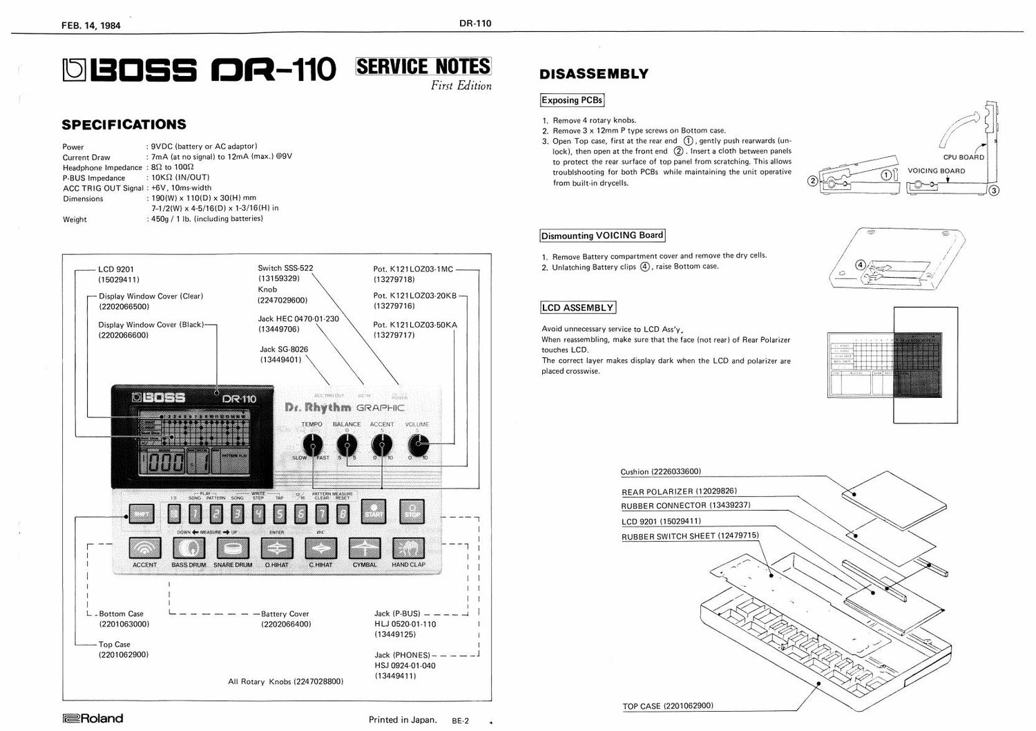
SPECIFICATIONS

Power

Current Draw
Headphone Impedance
P-BUS Impedance
ACC TRIG OUT Signal:
Dimensions

Weight

: QVDC (battery or AC adaptor)

: 7mA (at no signal) to 12mA (max) @9V
: 89 to 10052

:10Kfl (IN/OUT)

+6V, 10ms-width

:190(W)x110(D)x 30(H) mm

7-1/2(W) x 4-5/16(D) x 1-3/16(H) in

:4509 /1 lb. (including batteries)

DR-110

SERVIfiE L015;

First Edition

LCD 9201
(15029411)


(2202066500)


(2202066600)


Display Window Cover (Clear)

Display Window Cover (Black)

Switch 333522
(1 31 59329)
Knob
(2247029600)


Jack HEC 0470-01 230
(13449706)

Jack SG-8026

(13449401) \

__¥}r. Rhythm (5521;9ch

Tempo aALANCE mm (lemma
0-,._ »,a« _:>

Pot. K121 LOZO3-1MC
(13279718)

Pot. K121 LOZ03v20KB
(13279716)

Pot. K121 LOZOS-SOKA
(13279717)

(
M _ I
l- - ~ 0, I
| ) I
I I l
l l l
' i l
: i l
l

L .Bottom Case )- - Battery Cover Jack (P~BUS) - - - _ -l (
(2201063000) (2202066400) HLJ 0520-01410 1
(13449125) (
Top Case 1
(2201062900) Jack (PHONES) _____ J

HSJ 0924-01-040

All Rotary Knobs (2247028800) 3449 1)
@Roland Printed in Japan. 352 .

DISASSE MB LY
Exposing P083

1. Remove 4 rotary knobs.
2. Remove 3 x 12mm P type screws on Bottom case.

3. Open Top case, first at the rear end (D , gently push rearwards (un~
lock), then open at the front end @. lnsert a cloth between panels
to protect the rear surface of top panel from scratching. This allows
trOUblshooting for both PCBs while maintaining the unit operative

from built-in drycells.

Dismounting VOICING Board

1. Remove Battery compartment cover and remove the dry cells.

2. Unlatching Battery clips @ raise Bottom case.

LCD ASSEMBLY

Avoid unnecessary service to LCD Ass'y,

When reassembling, make sure that the face (not rear) of Rear Polarizer

touches LCD.

The correct layer makes display dark when the LCD and polarizer are

placed crosswise.

Cushion (2226033600)

REAR POLARIZER (12029825)
RUBBER CONNECTOR (13439237)

LCD 9201 (15029411)

TOP CASE (2201062900)

RUBBER SWITCH SHEET (12479715)

CPU BOARD

®B VOICING BOARD
®k oar-7 rr©~gi

Page 2

DR-l10

FEB. 14, 1984

CIRCUIT DESCRIPTIONS

CPU ICI

HD44790A44 is a 2K word by 4 hit one chip CMOS microcomputer equip-

ped with internal LCD drivers.

umfinazfitxnznmnfizptsuzte:
assessasssseéssssssssws
fiflflfilfllflflfifilflflflflfiflfilflflfiflflflfl3

Ill/71 El see It)
R117 E 525 11
R11 E SE6 3
m 3 I: 1 E its 7
111: El SEGG
km E sis:
I E 3564
HD44790A44 1
Reg E 5242
is» E 5551
R31 E tar14
R32 JAPAN E CONS
R31 1: 51mg
00 33 COMI
or El Va
D2 3] V:

HHHHHHHHHHHHHHHEHHHHEHE
m a u n.
"£32222323§s§§§§£5§:;§glg.
5: t 3 e > x >
CPU HDM790A-44 PIN FUNCTIONS
Symbor Name Description
ago
:3; input Port Head .n Key switches and TEMPO CLOCK,
no:
R10 T
R11 External Memory Data Bus
R12 (Rhythm patterns A/B. Songs I/III
R13
R20 1/0 Port
R21
1122
R23 External Memory Address Bus
R30 P2042} Used as OUTPUT Pan.
:3; cm
H33
D0
or
o2 Output Switches and Tempo Clock Scanning signals.
03
D4
05
D6
D7 Desr'eie 1/0 lerminals Memory ChIpSelect
DB NWT-4
09 on 1'
D10 SD
D B 0mm Trigger pulse 10 VOICEs
D12 Ac
D13 cy
D14 cpl
D15 CPII
INTO r1 ln ut for Swnch Scanmn
INTI "mm ("W5 SgeENugullegup Internally q

RESET Reset Input

Accepts Aoomswmm pulse on Power up

HLT Halt input

When "low", the CPU retains ail lhlemal
crrcult status as they are

TEST Test Input

No customer usable terminalt

v1
v2 LcD DC Supply Inputs Used as LCD driver signals,
v3
Vcc DC Supply Input +5v (110%) also used as LCD Dc slippIy
GND Ground Input GND
SE0 1
1 SEGMENT Outputs Output LCD drlve signals
sec 32
COM 1
1 Common Outputs Output LCD drwe Signals n~. 1/4 duly, 1/3 bias.
COM 4

SWITCH MATRIX (See Fig below)

(D The CPU enters external Interrupt routine on a rising edge of WT CLK
from lCZa, b which also serve as a part of CY Sound Generator, and reads
in TEMPO CLK and key switches through ports 00-03 and through
ROO-RO3.

(2) In reading the aboves, the CPU first turns ports D0-D3 "H", cutting off
D5A-D8A, DSB-DSB and D1 B-D4B, disconnecting the diodes from lC3
NAND gates and the ports ROG-R03 With an H being applied on one
input pin, each gate of |C3 will turn its output to "L" when the other in»
put pin is H (closing of STOP, START or BANK, or during H period of
TEMPO CLK). Ports ROG-R03 are pulled up internally and go low when
their mate lC3 outputs turn to L.

© Next, the CPU |C1 sets port D0 to L" which pulls one inputs of 1C3
down to low, turning all |C3 outputs to "H", reverse biasing D1A-D4A
which in turn isolate lCS from the read-in ports. Each of ports ROD-R03
can be connected to port DO through closed contacts (of CH, OH, SD or
BD) and through DBB. Then the program returns to the main routine.

@ On the next rising edge of INT CLK, the program enters interrupt routine
again and gates IC3.

Having reading lC3 outputs, this time the program sets D1 to L and reads
SHIFT, CP, CY and AC switches through R0 ports.

The CPU repeats the same procedures for the remaining D ports and returns
to (D, cycling TEMPO CLK, STOP, START and BANK readings at 2.2ms in-
ternals, and other switch groups at 8.8ms intervals.

l<--- 8.8msafl
H 2.2ms

DSA-DBA

anodes

MEMORY BACKUP

lCZ uPD444C is a 1K-word by 4 bits static RAMs It is used in DR-HO for
storing BANKS A/B, SONGS MI and STEPS 12/16 data, (BANKs C/D con-
taining factoryAset rhythms are stored into CPU's internal ROM) The RAM
memory is backed up by bUilt-in battery which bypasses power switch and
connects to RAMs VCC, 'W-E and Cg pins.

RAM READ 63 "*I___l-
ACCESS TMNG DATA--C:>-"

E -l T;
WRITE vT/E _l_.l__
DATA-C:>--

During the power OFF gL-T pin of ICi CPU is kept L, maintaining all its in-
put and output pins high impedance, isolating its circuits from peripheral
circuits and thus retains all the data so far obtained. When the CPU is re-
powered, it initializes internal circuits but still keeps some data intact

LCD

Each segment in LCD has a pair of electrodes. Electrodes on one glass plate
are grouped into four common (COM) terminals and the other plate ele-
ctrodes into SEGs as shown below.

No. COMi I con: i coma con/14 l No COMil COM? l COMErLgfl/M
c1 com . 15 II 19 1n 153
0,2 con/12 1e 1 '. 11 la l 1675
c3 7 17 ; 16-1 162 163 1674
CA A 13 151 152 15,3 154
1 TArw. . 4n 771 A 175 19 ,, 141 , 14.727 7 714.3 14.4
2 STEPW- 48, 4C .. 131 1312 130 1374
3 ,,,59N,GW: 49 , {1 » 12-1 122 p 12': 124
4 .. PATP , 4r 4a 4-5 3? 111 11-2 , 11a 1 4
s isono v.7 3a A 55 V23 1114 102 10.3
e 13 3e SC 6-5 24 91 9-2 9-3
7 c 39 31) _ 7 5 25 3.1 872 as
a 8 3r 39 _, . 875 26 71 7.2 7.3
e A 2d >77 as 37, e1 5 2 as
10 T1 ,4. <29 2c 1075 28 51 52 , 3s
11 T2 29 2b 1175 29 4-1 42 43
12 Ac 2r 23 1275 > 30 3",; 3-2 3 3
13 or ' 1d 777 135 31 2.1 272 2,3
14 Moe-WWI ie 1: 145 32 , 1.1 1.2 1.3
, ~n
I J7 UM flllllfl HILL] J [UL _h ___ w __ a
/ WWW,
l 'TZ qu
I 9 8 7 6 5 4 3 2 1
. . . . . . . .1
. . . . . . . . . 2
. O . . . . . . . 3
. . . . . . . C . 4
l . . . . . . . . O 5
111 12) la) 14) SONG PLAY
l I f'a-b A "' PATTERN PLAY
I
l B SONG WRITE
- H 43.; g ' STEP WRITE
I TAP WRITE
1\__k,, W _7, V- _ _ ,v._ v.._,_/
umummtm THU-U- m TL] _ - _ _
pm " 1 i '2
.
gv-V'FP:SUCMLA ma- 0 O 0 l)
com
5.4V Vcc-
435v VIA
3.3V v2w
2.25v v3-

com 2 ELI-J7

WM h

COM 4

COMl-COM4 WAVEFORMS Br TIMING