Page 1
2
Mar. 2006 AC-3
Cautionary Notes
Before beginning the procedure, please read
through this document.
No User Data
This product cannot save user data. Backing up user data during servicing is
not required.
Parts List
A component whose part code is ******** cannot be supplied as a service part
because one of the following reasons applies.
- Because it is supplied as an assembled part (under a different part code).
- Because a number of circuit boards are grouped together and supplied as
a single circuit board (under a different part code).
- Because supply is prohibited due to copyright restrictions.- Because reissuance is restricted.
- Because the part is made to order (at current market price).
Part Replacement
When replacing components near the power-supply circuit or a heat-
generating circuit (such as a circuit provided with a heat sink or including a
cement resistor), carry out the procedure according to the instructions with
respect to the part number, direction, and attachment position (mounting so as
to leave an air gap between the component and the circuit board, etc.).
Circuit Diagram
In the circuit diagram, NIU is an abbreviation for NOT IN USE. The circuit
board and circuit-board diagram show silkscreened indications, but no
components are mounted.
Specifications
AC-3: Acoustic Simulator
Nominal Input Level
20 dBu
Input Impedance
1 MΩ
Nominal Output Level
20 dBu
Output Impedance
1 kΩ
Recommended Load Impedance
10 kΩ or greater
Controls
Pedal switch, LEVEL knob, REVERB knob, BODY knob, TOP knob, MODE
knob
Indicators
CHECK indicator (Serves also as battery check indicator)
Connectors
INPUT jack, LINE OUT jack, G.AMP OUT jack, AC adaptor jack (DC 9 V)
Power Supply
DC 9 V: Dry battery/9 V type (6F22 (carbon), 6LR61 (alkaline)), AC Adaptor
(PSA-series: optional)
Current Draw
39 mA (DC 9 V)
* Expected battery life under continuous use:
Carbon: 3 hours, Alkaline: 10 hours
These figures will vary depending on the actual conditions of use.
Dimensions
73 (W) x 129 (D) x 59 (H) mm
2-7/8 (W) x 5-1/8 (D) x 2-3/8 (H) inches
Weight
440 g /1 lb (including battery)
Accessories
Owners Manual English (#G6027114R0)
Leaflet (USING THE UNIT SAFELY, IMPORTANT NOTES, and
Information) (#********)
Dry battery/9 V type (6LR61) (#********)
* The battery that was supplied with the unit is for temporary use intended
primarily for testing its operation. We also suggest replacing this with an
alkaline dry cell.
Option
AC Adaptor (PSA-series)
* 0 dBu = 0.775 Vrms
* In the interest of product improvement, the specifications and/or appearance of
this unit are subject to change without prior notice.
Page 2
3
Mar. 2006 AC-3
Location of Controls
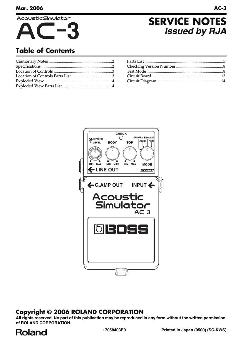
fig.panel.eps
Location of Controls Parts List
LEVELREVERB
INPUT LINE OUT
G.AMP OUT
10
9
8
7
6
5
4
3
2
1
14 13 12 11
No. Part Code Part Name Description Qty 1 22480220R0 P R-KNOB BF BLK/LCG (INTERNAL) 1 22480221R0 P R-KNOB S BLK/LCG (EXTERNAL) 1 F3279854R0 POTENTIOMETER RD912D-20-20FWH-B54-6009 1 H5039521R0 NUT M7 4 2 F3449707R0 LINE OUT JACK HTJ-064-12DS 1 H5039510R0 NUT M9X12X2T NI 4 H5039112R0 WASHER 9X14X0.5 NI 4 3 13449140R0 JACK (STEREO) HTJ-064-14D 1 H5039510R0 NUT M9X12X2T NI 4 H5039112R0 WASHER 9X14X0.5 NI 4 4 75D932T0R0 PEDAL 1 5 22357304R0 PEDAL PLATE 1 6 H5029820R0 THUMB SCREW 3X10 FEBC 1 7 13449104R0 INPUT JACK HTJ-064-13D 1 H5039510R0 NUT M9X12X2T NI 4 H5039112R0 WASHER 9X14X0.5 NI 4 8 F3279853R0 POTENTIOMETER RD901-20-15FP-B54K-04 1 22480260R0 P R-KNOB MF BLK/LCG 3 H5039521R0 NUT M7 4 9 F3279852R0 POTENTIOMETER RD901-20-15FW-B54-006 2 22480260R0 P R-KNOB MF BLK/LCG 3 H5039521R0 NUT M7 4 10 G2217758R0 PANEL 1 11 75D933C0R0 CASE 1 12 15029281R0 LED L-34HDSL 1 13 13449717R0 ADAPTOR JACK HEC2392-01-150 1 14 22537538R0 PSA LABEL 8X13 1