This is the 21 pages manual for bose sounddock 10 top. Read or download the pdf for free.
If you want to contribute, please mail your pdfs to info@audioservicemanuals.com.
Page: 1 / 21
Extracted text from bose sounddock 10 top (Ocr-read)
Page 1
SoundDock 10 Theory of Operation
2
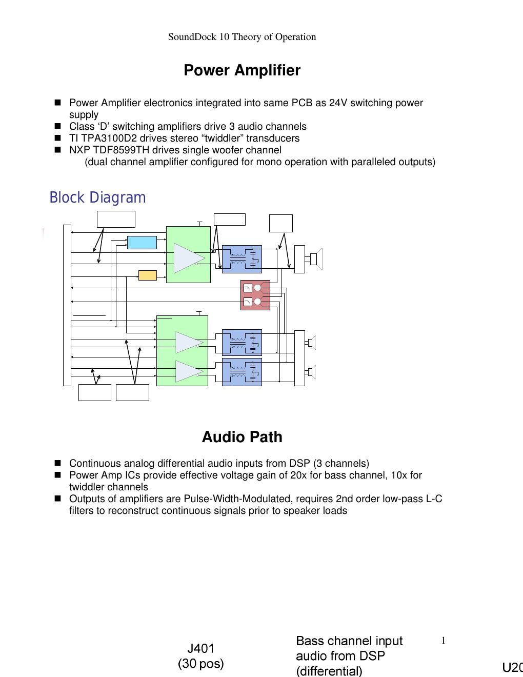
Amplifier Characteristics
- Supply voltage: +24V
- Full scale output (after filter):
- 18V peak into 1.5 ohms for bass
- 14V peak into 3.5 ohms for twiddlers
- Full scale input from DSP:
- 0.95V for bass
- 1.5V for twiddler channels
- PWM switching frequency: 288kHz
- Synchronized to PA_SYNCH_CLK provided by DSP
- PWM modulation mode: BD
Bass Amplifier Configuration
- Slave mode for externally supplied clock
- Internal PLL disabled
- BD modulation
- I2C bus disabled
- Paralleled outputs
- Load detection and DC offset protection disabled
Twiddler Amplifier Configuration
- Slave mode for externally supplied clock
- Gain set to 20dB (GAIN0 and GAIN1 pins grounded)
- Uses internal PLL (cannot be disabled)
Output Filters
- 2nd order low-pass L-C
- Inductor is planar construction - inductor windings formed by PCB traces, ferrite
core is glued to PC board
- Provide large common mode inductance (20 to 50uH) needed for attenuation of
large common mode voltage swing present in BD modulated output stage
Page 2
SoundDock 10 Theory of Operation
3
Output Filters
Twiddler channels:
- Nominal diff mode inductance: 11.5uH
- Capacitance: 0.5uF
- Resonant frequency: ~66kHz
- DM attenuation at 288kHz: >20dB
- CM attenuation at 288kHz: >40dB
- C332, C334, and R317 provide damping for common-mode transients on start-up
Bass channel:
- Nominal diff mode inductance: 7.5uH
- Capacitance: 2uF
- Resonant frequency: ~40kHz
- DM attenuation at 288kHz: >30dB
- CM attenuation at 288kHz: >40dB