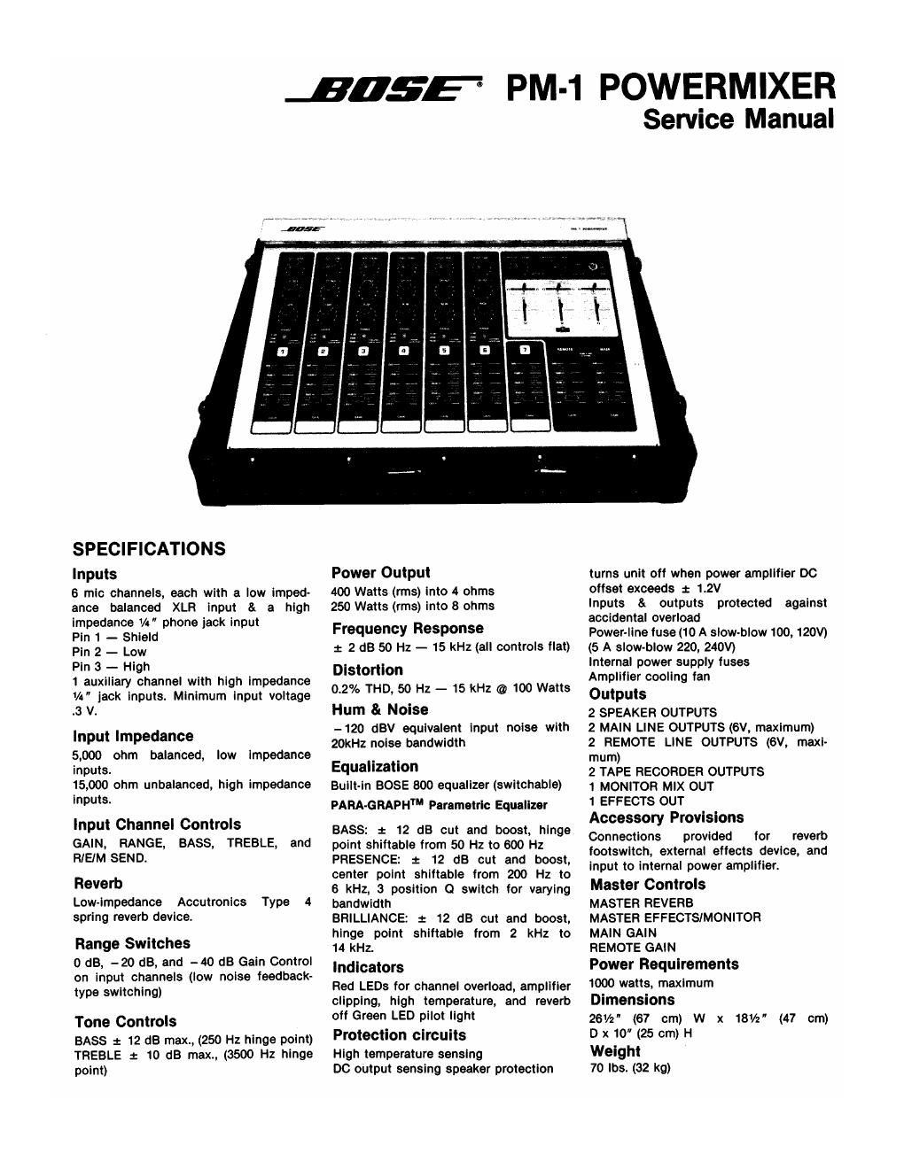
Bose pm 1 power mixer

This is the 18 pages manual for bose pm 1 power mixer.
Read or download the pdf for free. If you want to contribute, please mail your pdfs to info@audioservicemanuals.com.

Page: 1 / 18
left right
bose pm 1 power mixer

Extracted text from bose pm 1 power mixer (Ocr-read)


Page 1

1055- PM-1 POWERMIXER

Service Manual

SPECIFICATIONS

inputs

8 mic channels, each with a low imped-
ance balanced XLR input a a high
impedance Vt" phone jack input

Pin 1 - Shield

Pin 2 - Low

Pin 3 - High

1 auxiliary channel with high impedance
V4" jack inputs. Minimum Input voltage
.3 V

input impedance
5,000 ohm balanced,
inputs.

15,000 chm unbalanced, high impedance
inputs.

low impedance

Input Channel Controls

GAIN, RANGE, BASS. TREBLE, and
RIEIM SEND.

Reverb

Low-Impedance Accutronics Type 4
spring revarb device.

Range Switches

0 dB, -20 dB, and -40 dB Gain Control
on input channels (low noise feedback-
type switching)

Tone Controls

BASS : 12 dB max., (250 Hz hinge point)
TREBLE 1: 10 dB max., (3500 Hz hinge
point)

Power Output

400 Watts (rms) into 4 ohms
250 Watts (me) into 8 ohms

Frequency Response
x 2 d8 50 Hz - 15 kHz (all controls flat)

Distortion
0.2% THD, so Hz - 15 kHz @ 100 Watts

Hum 81 Noise

-120 dBV equivalent Input noise with
20kHz noise bandwidth

Equalization
Built-in BOSE 800 equalizer (switchable)
PARA-GRAPH Parametric Equalizer

BASS: t 12 dB cut and boost, hinge
point shiftabie from 50 Hz to 600 Hz
PRESENCE: 2 12 (13 cut and boost,
center point ahiftable from 200 Hz to
6 kHz, 3 position Q switch for varying
bandwidth

BRILLIANCE: : 12 dB out and boost,
hinge point shlitable from 2 kHz to
14 kHz.

Indicators

Red LEDs for channel overload, amplifier
clipping, high temperature, and reverb
off Green LED pilot light

Protection circuits

High temperature sensing
DC output sensing speaker protection

turns unit off when power amplifier 00
offset exceeds : 1.2V

Inputs & outputs protected against
accidental overload

Power-line fuse (10 A slow-blow 100, 120V)
(5 A slow-blow 220, 240V)

Internal power supply fuses

Amplifier cooling fan

Outputs

2 SPEAKER OUTPUTS

2 MAIN LINE OUTPUTS (6v, maximum)

2 REMOTE LINE OUTPUTS (6V, maxi-
mum)

2 TAPE RECORDER OUTPUTS

1 MONITOR MIX OUT

1 EFFECTS OUT

Accessory Provisions

Connections provided for reverb
footswltcn, external effects device, and
input to Internal power amplifier.
Master Controls

MASTER REVERE

MASTER EFFECTS/MONITOR
MAIN GAIN

REMOTE GAIN

Power Requirements

1000 watts, maximum
Dimensions

261/2 (67 cm) W x 181/2"
D x10 (25 cm) H

Weight

70 lbs. (32 kg)

(47 cm)

Page 2

DISASSEMBLY PROCEDURE

CONTROL PANEL ASSEMBLY
1. Remove 5 Phillips-head screws with dress washers from front of case.

2. Remove 4 Phillips-head screws with insulating nylon shoulder washers holding the control panel
to the main chassis. The control panel assembly is now free to be lifted up and back.

INPUT BOARD

1. Remove 4 Phillips-head screws holding the metal shield over the input boards. Note: These are
special nylok screws for vibration resistance.

2. Pull off the control knobs. Remove hex nuts and lockwashers from R/EIM SEND, TREBLE and
BASS controls. Remove 2 Phillips-head screws and washers from each GAIN slider control. The
Input board is now free to be removed.

MAIN PC BOARD

1. Remove 3 Phillips-head screws holding the metal shield over the Main PC board.

2. Remove all controls knobs, hex nuts, washers, and screws from the following controls: Master
Reverb, Master EFF/MON, Parametric Equalizer, Gain #7, Remote Gain and Master Gain. Remove
5 Phillips-head screws. The Main PC board is now free to be removed.

POWER AMPLIFIER AND FAN

1. Remove 4 Phillips-head screws holding the metal shield over the Power Amplifier board and remove
the shield. Carefully locate the 4 metal spacers between the shield and heat sink assembly.

2. Lift up the Power Amplifier board to gain access to the fan. The component side of the Power
Amplifier board is now opened by lifting off the fan shroud. When reassembling be careful not to
bend the leads of the PC mounted components.

REVERB UNIT

1. Complete steps 1 and 2 and remove 4 Castle head nuts holding the Reverb assembly in place. To
gain access to the internal components at the Reverb assembly, remove the 4 Castle head nuts
and 8 Phillips-head screws. When reinstalling be careful to tighten the 4 Castle head nuts evenly
to space reverb 3/ " off lower chassis at all four (4) corners. Route input and output cables so as
not to touch outer channel of reverb.

MAIN CHASSIS

1. The entire main chassis can be removed, if necessary, by removing 6 large Phillips-head screws
and the 4 Phillips-head screws holding the power transformer in place. Be careful to route Reverb
HO and Power Amplifier input cables as far from transformer as possible to prevent hum pick-up.

NOTE: - Front panel assembly and main chassis are electrically isolated with nylon washers. When
reassembling the unit, the washers must be used to prevent ground loops and resulting hum.

Loosely install 5 Phillips-head screws in front of case. Tighten 4 Phillips-head screws with nylon shoulder
washers only until front panel edge lines up with edge of case. Now firmly tighten the 5 screws in front
of case.