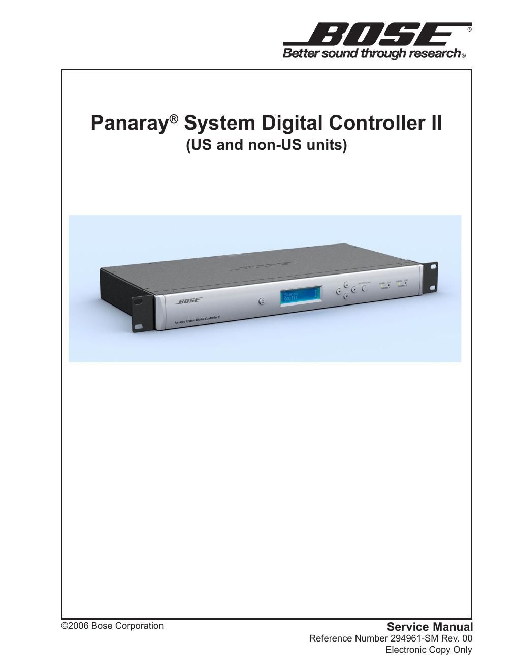
Bose panaray 294961 service manual r0 bose psdc ii

This is the 65 pages manual for bose panaray 294961 service manual r0 bose psdc ii.
Read or download the pdf for free. If you want to contribute, please mail your pdfs to info@audioservicemanuals.com.

Page: 1 / 65
left right
bose panaray 294961 service manual r0 bose psdc ii

Extracted text from bose panaray 294961 service manual r0 bose psdc ii (Ocr-read)


Page 1

1 CONTENTS Safety Information ............................................................................................................................. 2 Warranty............................................................................................................................................. 2 Product Description .......................................................................................................................... 3 Specifications .................................................................................................................................... 4 Electrostatic Discharge Sensitive (ESDS) Device Handling ......................................................... 5 Part List Notes ................................................................................................................................... 5 Packaging Part List, Panaray ® Digital Controller II (see Figure 1) ............................................... 6 Figure 1. Panaray Digital Controller II Packaging View ....................................................................6 Main Part List, Panaray System Digital Controller II (see Figure 2) ............................................. 7 Figure 2. Panaray System Digital Controller II Exploded View .........................................................8 Main Part List, Front Panel Sub-assembly (see Figure 3) ............................................................. 9 Figure 3. Front Panel Sub-assembly Exploded View .......................................................................9 Electrical Part Lists ................................................................................................................... 10-26 Digital Signal Processor (DSP) PCB Assembly ...................................................................... 10-15 Input/Output PCB Assembly .................................................................................................... 16-20 Button and LED PCB Assembly .....................................................................................................21 Switch PCB Assembly .................................................................................................................... 22 Switch Mode Power Supply (SMPS) PCB Assembly ............................................................. 23-26 Disassembly Procedures .........................................................................................................27-28 Test Procedures ........................................................................................................................ 29-30 Figure 4. DSP PCB Top Etch Layer and Component Layout .........................................................31 Figure 5. DSP PCB Internal Etch Layer 1 and Component Layout ................................................32 Figure 6. DSP PCB Internal Etch Layer 2 and Component Layout ................................................33 Figure 7. DSP PCB Bottom Etch Layer and Component Layout ....................................................34 Figure 8. Input/Output PCB Top Etch and Component Layout .......................................................35 Figure 9. Input/Output PCB Bottom Etch and Component Layout .................................................35 Figure 10. Button and LED PCB Top Etch and Component Layout ...............................................36 Figure 11. Button and LED PCB Top Etch and Component Layout ...............................................36 Figure 12. Standby Switch PCB Top Etch and Component Layout ................................................36 Figure 13. Standby Switch PCB Bottom Etch and Component Layout ..........................................36 Figure 14. Switch Mode Power Supply PCB Top Etch and Component Layout .............................37 Figure 15. Switch Mode Power Supply PCB Bottom Etch and Component Layout .......................37 Software Update Installation Procedure ................................................................................. 38-40 Panaray Digital Controller II EQ Curves .................................................................................. 41-54 Theory of Operation .................................................................................................................. 55-57 Panaray Digital Controller II Block Diagram ................................................................................. 58 Integrated Circuit Diagrams ..................................................................................................... 59-61 Service Manual Revision History ................................................................................................... 62

Page 2

2 SAFETY INFORMATION 1. Parts that have special safety characteristics are identified by the symbol on schematics or by special notes on the parts list. Use only replacement parts that have critical characteristics recommended by the manufacturer. 2. Make leakage current or resistance measurements to determine that exposed parts are acceptably insulated from the supply circuit before returning the unit to the customer. Use the following checks to perform these measurements: A. Leakage Current Hot Check-With the unit completely reassembled, plug the AC line cord directly into a 120V AC outlet. (Do not use an isolation transformer during this test.) Use a leakage current tester or a metering system that complies with American National Standards Institute (ANSI) C101.1 "Leakage Current for Appliances" and Underwriters Laboratories (UL) UL6500 / UL60065 / IEC 60065 paragraph 9.1.1. With the unit AC switch first in the ON position and then in OFF position, measure from a known earth ground (metal waterpipe, conduit, etc.) to all exposed metal parts of the unit (antennas, handle bracket, metal cabinet, screwheads, metallic overlays, control shafts, etc.), especially any exposed metal parts that offer an electrical return path to the chassis. Any current measured must not exceed 0.5 milliamp. Reverse the unit power cord plug in the outlet and repeat test. ANY MEASUREMENTS NOT WITHIN THE LIMITS SPECIFIED HEREIN INDICATE A POTENTIAL SHOCK HAZARD THAT MUST BE ELIMINATED BEFORE RETURNING THE UNIT TO THE CUSTOMER. B. Insulation Resistance Test Cold Check-(1) Unplug the power supply and connect a jumper wire between the two prongs of the plug. (2) Turn on the power switch of the unit. (3) Measure the resistance with an ohmmeter between the jumpered AC plug and each exposed metallic cabinet part on the unit. When testing 3 wire products, the resistance measured to the product enclosure should be between 2 and infinite MOhms. Also, the resistance measured to exposed input/output connectors should be between 4 and infinite MOhms. When testing 2 wire prod- ucts, the resistance measured to exposed input/output connectors should be between 4 and infinite MOhms. If it is not within the limits specified, there is the possibility of a shock hazard, and the unit must be repaired and rechecked before it is returned to the customer. CAUTION: The Bose ® Panaray ® System Digital Controller II contains no user-serviceable parts. To prevent warranty infractions, refer servicing to warranty service stations or factory service. PROPRIETARY INFORMATION THIS DOCUMENT CONTAINS PROPRIETARY INFORMATION OF BOSE CORPORATION WHICH IS BEING FURNISHED ONLY FOR THE PURPOSE OF SERVICING THE IDENTIFIED BOSE PRODUCT BY AN AUTHORIZED BOSE SERVICE CENTER OR OWNER OF THE BOSE PRODUCT, AND SHALL NOT BE REPRODUCED OR USED FOR ANY OTHER PURPOSE. The Bose Panaray System Digital Controller II is covered by a limited 1-year transferable limited warranty. Warranty period for Europe is 2 years. WARRANTY