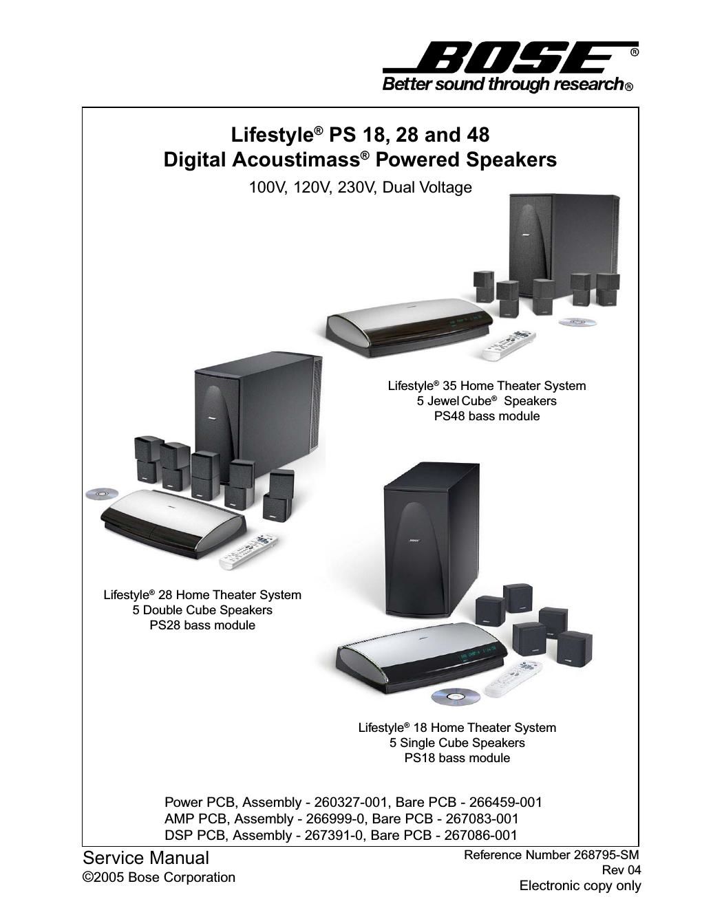
Bose lifestyle ps 18 28 and 48 268795 service manual rev04 part list

This is the 43 pages manual for bose lifestyle ps 18 28 and 48 268795 service manual rev04 part list.
Read or download the pdf for free. If you want to contribute, please mail your pdfs to info@audioservicemanuals.com.

Page: 1 / 43
left right
bose lifestyle ps 18 28 and 48 268795 service manual rev04 part list

Extracted text from bose lifestyle ps 18 28 and 48 268795 service manual rev04 part list (Ocr-read)


Page 1

1PS18/28/48 Service Manual PROPRIETARY INFORMATION THIS DOCUMENT CONTAINS PROPRIETARY INFORMATION OF BOSE ® CORPORATION WHICH IS BEING FURNISHED ONLY FOR THE PURPOSE OF SERVICING THE IDENTIFIED BOSE PRODUCT BY AN AUTHORIZED SERVICE CENTER OR OWNER OF THE BOSE PRODUCT, AND SHALL NOT BE REPRODUCED OR USED FOR ANY OTHER PURPOSE. Warranty The Lifestyle ®PS18/28/35 powered speaker system is covered by a limited 1-year transferable warranty. Contents Safety Information ............................................................................................................................. 2 Electrostatic Discharge Sensitive Device Handling (ESDS) ......................................................... 2 Specifications .................................................................................................................................... 3 Part List Notes ................................................................................................................................... 4 Part List Table of Contents ............................................................................................................... 4 Lifestyle ® 18 Home Theater System Packaging .............................................................................. 5 Figure 1. LS18 System Packaging Exploded View ..............................................................................5 Lifestyle ® 28 Home Theater System Packaging .............................................................................. 6 Figure 2. LS28 System Packaging Exploded View ..............................................................................6 Lifestyle ® 35 Home Theater System Packaging .............................................................................. 7 Figure 3. LS35 System Packaging Exploded View ..............................................................................7 Lifestyle ® 18/28/35 Essentials Kit Part List ..................................................................................... 8 Figure 4. LS18, 28, 35 Essentials Kit Exploded View ..........................................................................9 Lifestyle ® 18 Lit Kit Part List ..........................................................................................................10 Lifestyle® 28 Lit Kit Part List ..........................................................................................................10 Lifestyle® 35 Lit Kit Part List ..........................................................................................................10 Lifestyle® 18 Single Cube Speaker, 5 Pack Packaging List ......................................................... 11 Lifestyle® 28 Double Cube Speaker, 5 Pack Packaging List ........................................................ 11 Lifestyle® 35 Jewel Cube ® Speaker, 5 Pack Packaging List ........................................................ 11 Figure 5. LS18, 28 Cube Pack Exploded View ..................................................................................12 Figure 6. LS35 Cube Pack Exploded View ........................................................................................12 Jewel Cube Part List ....................................................................................................................... 13 Figure 7. Jewel Cube Exploded View ................................................................................................13 Single and Dual Cube Speaker Part List ....................................................................................... 14 Figure 8. Cube Exploded View ..........................................................................................................14 PS18/28/48 Bass Module Assembly Part List ............................................................................... 15 Figure 9. Bass Module Exploded View ..............................................................................................15 PS18/28/48 Amplifier Module Assembly Part List ........................................................................ 16 Figure 10. Amplifier Module Exploded View ......................................................................................16 PS18/28/48 Electrical Part List ................................................................................................. 17-31 Setting up a computer to issue TAP commands .......................................................................... 32 Figure 11. Test cable part number 264564 ........................................................................................33 Placing the Bass Module into TAP Mode ...................................................................................... 34 Figure 12. DIP switch Up/Down orientation .......................................................................................34 Setting the Equalizer ...................................................................................................................... 34 Test Procedures ........................................................................................................................ 35-36 Bass Module Disassembly Procedures .................................................................................. 37-38 Cube Speaker Disassembly Procedures ...................................................................................... 39 Figure 13. PCB Part Number Identification .......................................................................................40 Figure 14. Date Of Manufacture (DOM) Identification .......................................................................40

Page 2

2PS18/28/48 Service Manual 1. Parts that have special safety characteristics are identified by the symbol on schematics or by special notes on the parts list. Use only replacement parts that have critical characteristics recommended by the manufacturer. 2. Make leakage current or resistance measurements to determine that exposed parts are accept- ably insulated from the supply circuit before returning the unit to the customer. Use the following checks to perform these measurements: A. Leakage Current Hot Check-With the unit completely reassembled, plug the AC line cord directly into a 120V AC outlet. (Do not use an isolation transformer during this test.) Refer to UL6500 paragraph 9.1.1. Use a leakage current tester or a metering system that complies with American National Standards Institute (ANSI) C101.1 Leakage Current for Appliances and Underwriters Laboratories (UL) 6500, IEC 60065 paragraph 9.1.1. With the unit AC switch first in the ON position and then in OFF position, measure from a known ear th ground (metal waterpipe, conduit, etc.) to all exposed metal parts of the unit (antennas, handle bracket, metal cabinet, screwheads, metallic overlays, control shafts, etc.), especially any exposed metal parts that offer an electrical return path to the chassis. Any current measured must not exceed 0.5 milliamp. Reverse the unit power cord plug in the outlet and repeat test. ANY MEASUREMENTS NOT WITHIN THE LIMITS SPECIFIED HEREIN INDICATE A POTENTIAL SHOCK HAZARD THAT MUST BE ELIMINATED BEFORE RETURNING THE UNIT TO THE CUSTOMER. B. Insulation Resistance Test Cold Check-(1) Unplug the power supply and connect a jumper wire between the two prongs of the plug. (2) Turn on the power switch of the unit. (3) Measure the resistance with an ohmmeter between the jumpered AC plug and each exposed metallic cabinet part on the unit. When testing 3 wire products, the resistance measured to the product enclosure should be between 2 and infinite Meg ohms. Also, the resistance measured to exposed output/ input connectors should be between 4 and infinite Meg ohms. When testing 2 wire products, the resistance measured to exposed output/input connectors should be between 4 and infinite Meg ohms. If it is not within the limits specified, there is the possibility of a shock hazard, and the unit must be repaired and rechecked before it is RETURNED TO THE CUSTOMER. ELECTROSTATIC DISCHARGE SENSITIVE (ESDS) DEVICE HANDLING This unit contains ESDS devices. We recommend the following precautions when repairing, replacing or transporting ESDS devices: -Perform work at an electrically grounded work station. -Wear wrist straps that connect to the station or heel straps that connect to conductive floor mats. -Avoid touching the leads or contacts of ESDS devices or PC boards even if properly grounded. Handle boards by the edges only. -Transport or store ESDS devices in ESD protective bags, bins, or totes. Do not insert unpro- tected devices into materials such as plastic, polystyrene foam, clear plastic bags, bubble wrap or plastic trays. SAFETY INFORMATION CAUTION: THE BOSE ®PS 28 AND PS 35 POWERED SPEAKER CONTAINS NO USER-SER- VICEABLE PARTS. TO PREVENT WARRANTY INFRACTIONS, REFER SERVICING TO WARRANTY SERVICE STATIONS OR FACTORY SERVICE.