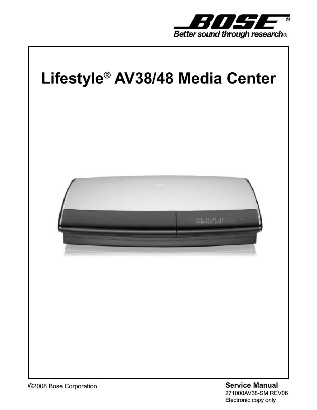
Page 1
2
1. Parts that have special safety characteristics are identified by the \
symbol on schematics or by
special notes on the parts list. Use only replacement parts that have critical characteristics recom-
mended by the manufacturer.
2. Make leakage current or resistance measurements to determine that exposed parts are acceptably
insulated from the supply circuit before returning the unit to the custo\
mer.
Use the following checks to perform these measurements:
A. Leakage Current Hot Check-With the unit completely reassembled, plug \
the AC line cord directly
into a 120V AC outlet. (Do not use an isolation transformer during this test.) Use\
a leakage current
tester or a metering system that complies with American National Standards Institute (ANSI) C101.1
Leakage Current for Appliances and Underwriters Laboratories (UL) 6500 / IEC 60056 paragraph
9.1.1. With the unit AC switch first in the ON position and then in OFF position, measure fro\
m a known
earth ground (metal waterpipe, conduit, etc.) to all exposed metal parts of the unit (antennas, handle
bracket, metal cabinet, screwheads, metallic overlays, control shafts, etc.), especially any exposed
metal parts that offer an electrical return path to the chassis. Any current measured must not exceed
0.5 milliamp. Reverse the unit power cord plug in the outlet and repeat \
test. ANY MEASUREMENTS
NOT WITHIN THE LIMITS SPECIFIED HEREIN INDICATE A POTENTIAL SHOCK HAZARD THAT
MUST BE ELIMINATED BEFORE RETURNING THE UNIT TO THE CUSTOMER.
B. Insulation Resistance Test Cold Check-(1) Unplug the power supply and connect a jumper wire
between the two prongs of the plug. (2) Turn on the power switch of the unit. (3) Measure the resis-
tance with an ohmmeter between the jumpered AC plug and each exposed metallic cabinet part on
the unit. When testing 3 wire products, the resistance measured to the product enclosure should be
between 2 and infinite MOhms. Also, the resistance measured to exposed input/output connectors
should be between 4 and infinite MOhms. When testing 2 wire products, the resistance measured to
exposed input/output connectors should be between 4 and infinite MOhms. \
If it is not within the limits
specified, there is the possibility of a shock hazard, and the unit must\
be repaired and rechecked
before it is returned to the customer.
ELECTROSTATIC DISCHARGE SENSITIVE (ESDS) DEVICE HANDLING
This unit contains ESDS devices. We recommend the following precautions when repairing,
replacing or transporting ESDS devices:
Perform work at an electrically grounded work station.
Wear wrist straps that connect to the station or heel straps that connect to conductive floor mats.
Avoid touching the leads or contacts of ESDS devices or PC boards even if properly grounded.
Handle boards by the edges only.
Transport or store ESDS devices in ESD protective bags, bins, or totes. D\
o not insert unprotected
devices into materials such as plastic, polystyrene foam, clear plastic \
bags, bubble wrap or plastic
trays.
SAFETY INFORMATION
Page 2
3
The AV38 and AV48 Media Center uses a hardware platform derived from the AV28 Media Center. It
uses the same plastic enclosure and external power supply unit ("floor \
wart"). Likewise, it is meant to
interface to the same home theater speaker system.
The AV38 and AV48 Media Center have an internal hard drive used for storing CDs.
AV38 - Stores 200 hours of music or over 200 CDs.
AV48 - Stores 340 hours of music or over 350 CDs.
The AV38 and AV48 Media Center is manufactured in two hardware configurations, Euro an\
d US:
Like the AV28 Media Center, the AV38 and AV48 Media Center is a self-contained DVD/CD/MP3 disc
player with an AM/FM tuner for use with Bose
® powered speaker systems. In addition to the two
internal sources (DVD/CD and AM/FM tuner), it allows playing up to four external audio sources: TV,
VCR, CAB/SAT, and AUX. A 27MHz (40MHZ for Euro), one-way RF remote control operates the unit
without line-of-sight restriction; provisions for infrared remote contro\
l of the Media Center also exist.
An integrated IR blaster allows limited control of other manufacturer's \
equipment (TV's, VCR's and
Cable/Satellite Set-Top boxes). The Media Center has two independent audio output zones (Main and
Bose
® Link), accessible through circular DIN connectors in the back of the p\
roduct.
The AV38 and AV48 Media Center contains five PCBs:
The AV38 and AV48 Media Center use a new smart speaker protocol and uses a 9 pin DIN s\
peaker
connector. The AV28 Media Center used an 8 pin DIN speaker connector. Support is limited for legacy
product with an 8 pin DIN.
PCB Assembly P/N
Main PCB 282491-010
IR PCB Contained on 282491-010
Headphone PCB Contained on 282491-010
Tuner PCB 273300-01x
Keypad PCB 277595-001
Product Description
Variant US EURO
SCART X
RDS X
TV On Detector X
Remote 27MHz RF 40MHz RF
FM Tuner US EURO
Software Update Information
The software in the AV38 and AV48 Media Center can be updated using a software update CD avail-
able from Bose service or downloaded at http://serviceops.bose.com. Refer to page 50, Console Key
Special Functions, to determine the software version of the unit. Refer to the Bose service extranet
site for information regarding the latest software revision; click on Lifestyle
®music centers and then
AV38/AV48 media center. http://serviceops.bose.com