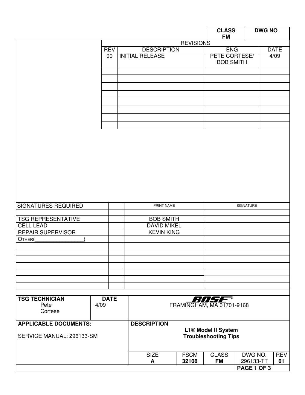
Bose l1 bose model ii system rev 01 troubleshooting tibose ps

This is the 3 pages manual for bose l1 bose model ii system rev 01 troubleshooting tibose ps.
Read or download the pdf for free. If you want to contribute, please mail your pdfs to info@audioservicemanuals.com.

Page: 1 / 3
left right
bose l1 bose model ii system rev 01 troubleshooting tibose ps

Extracted text from bose l1 bose model ii system rev 01 troubleshooting tibose ps (Ocr-read)


Page 1

Framingham, MA 01701-9168 SIZE A FSCM 32108 CLASS FM DWG NO. 296133-TT SHEET 2 of 3 REV. 01 Troubleshooting Tips L1® Model II System Refer to the L1® Model II System service manual reference number 296133-SM for schematics, PCB layouts and parts lists located on service web site. Preventative Repair Measures Note: Perform the following on all units returned for repair. Product Check Action L1 N/A There is no preventative maintenance for this product. Troubleshooting Tips Product Symptom Check Action L1 No bass output CN301 and J301 Verify that connectors CN301 / J301 are fully seated on the amplifier PCB. L1 Red indicator light turns on. CN300L2 Verify that all of the pins in connector CN300L2 are fully seated. L1 Red indicator light turns on after 5 seconds IC200 Check IC200 on the amplifier board related to the failure. IC200 is the half bridge driver IC for the amplifier section. L1 No audio, no signal LEDs lit. U108 Check A/D converter U108 located on the I/O PCB. Bose part # 271836. L1 L1 does not power up the T1 RJ45 connector Ethernet cable may not be making contact with J103 (RJ45 connector on the power stand). L1 No input signal available. Input / Output board. Check the output of op-amp U100B at pin 7. If the signal is good there, verify that CODEC U108B and associated circuitry is working by checking the outputs to the amplifier PCBs at connectors J301L and J301B. If the outputs are good, check the amplifier board for the affected channel. If the outputs are bad, troubleshoot the I/O board to the component level. If something other than the DSP IC is bad, replace the part. If the DSP IC (U110) is failed, replace the board. U110 is a BGA part and cannot be easily replaced.

Page 2

Framingham, MA 01701-9168 SIZE A FSCM 32108 CLASS FM DWG NO. 296133-TT SHEET 3 of 3 REV. 01 Troubleshooting Tips, continued Product Symptom Check Action L1 - System does not mute and then un-mute while passing an audio signal and connecting or disconnecting a B1 bass module. Audio may or may not sound incorrect as well. Input / Output / DSP PCB bass sensing circuit. - Check that resistors R311 and R312 are not open or damaged and that they are soldered properly. - Check that the pins of the J102 connector are properly soldered to the board. - Check ICs U111A, U108A and associated circuitry. Refer to sheet 1 of the DSP/IO PCB schematic diagram. L1 Fan noise A customer may complain that the fan comes on sporadically while using the system Power stand firmware. Connect a T1 ToneMatch Audio Engine to the L1 Model II power stand. Turn on the T1 and the L1. Rotate the selector knob on the T1 to PREFS. Press down on the knob located on the far left under the display to get to the Menu. Rotate the knob to scroll down to POWER STAND. Press the knob again to select Power Stand. Press the knob located under the right side of the display to select VERSIONS. You will see the firmware versions listed for the L1 Model II power stand. If firmware version 1.0 is shown, you will need to update the power stand firmware. You can also read the power stand firmware and voicing revisions by connecting the power stand as above and connecting the T1 to a computer using a USB cable. Once connected, open the L1 Updater Tool (refer to Section 4 of this repair package). On the Updater Tool screen you will see the firmware versions for the T1 and the power stand listed after the name of the file, i.e. Bose MM1 Firmware: 1.0. Update the power stand firmware as needed using the update procedure located later in the repair package or on page 54 of the service manual.