Bose l1 bose model i system troubleshooting tibose ps

This is the 3 pages manual for bose l1 bose model i system troubleshooting tibose ps.
Read or download the pdf for free. If you want to contribute, please upload pdfs to audioservicemanuals.wetransfer.com.

Page: 1 / 3
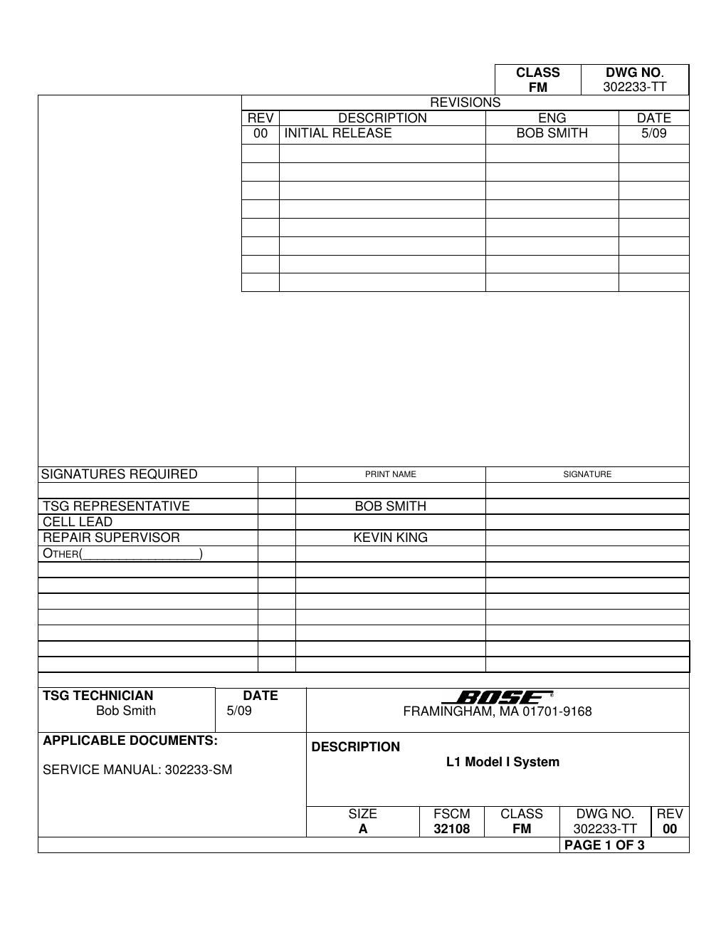
bose l1 bose model i system troubleshooting tibose ps

Extracted text from bose l1 bose model i system troubleshooting tibose ps (Ocr-read)


Page 1

Framingham, MA 01701-9168 SIZE A FSCM 32108 CLASS FM DWG NO. 302233-TT SHEET 2 of 3 REV. 00 Troubleshooting Tips L1 Model I System Refer to the L1 Model I System service manual, part number 302233-SM for schematics, PCB layouts and parts lists. Preventative Repair Measures Note: Perform the following on all units returned for repair. Product Check Action L1 Model I Power Stand Software Revision Update firmware and EQ presets to latest revision. Update instructions are located on the service intranet/extranet sites. L1 Model I Power Stand Inspect caps for visible damage Inspect caps C504, C505, C506 and C522 on the +/- 27V Power Supply boards. Check caps C802, C811, C857, C858, C909 and C910 on the amplifier board. Replace if defective. Troubleshooting Tips Product Symptom Check Action L1 Model I Power Stand Low / intermittent audio on one channel Channel 1 and 2 input trim pots One of the trim pots may be defective. AUX Power Supply PCB Dead unit Connectors CN613 and CN614 There may be solder fractures at connectors CN613 and CN614. Also inspect C610 for visible damage. AUX Power Supply PCB Dead unit Diodes D601, D605, D606, D607, D608 and D609 Using the below table as a guide, de-solder one side of the diodes listed and measure the resistance of each diode. REF DES MEASUREMENT EXPECTED READING IN OHMS D601 (+)ANODE (-) CATHODE 36K OHMS D601 (+) CATHODE (-) ANODE OPEN D605 (+)ANODE (-) CATHODE 30K OHMS D605 (+) CATHODE (-) ANODE OPEN D606 (+)ANODE (-) CATHODE 13K OHMS D606 (+) CATHODE (-) ANODE > 50MEG OHMS D607 (+)ANODE (-) CATHODE 13K OHMS D607 (+) CATHODE (-) ANODE > 50MEG OHMS D608 (+)ANODE (-) CATHODE 13K OHMS D608 (+) CATHODE (-) ANODE > 50MEG OHMS D609 (+)ANODE (-) CATHODE 1.3K OHMS D609 (+) CATHODE (-) ANODE 1.3MEG OHMS

Page 2

Framingham, MA 01701-9168 SIZE A FSCM 32108 CLASS FM DWG NO. 302233-TT SHEET 3 of 3 REV. 00 Troubleshooting Tips, continued Product Symptom Check Action AUX Power Supply PCB Dead Unit R607, R608 Check for open resistors, R607, R608. VCC to IC601 will be missing. AUX Power Supply PCB Fans constantly on, or not working at all Q603 Q603 may be defective. Replace if fans are not working properly. EMI PCB Dead Unit EMI PCB Check for burnt thermistors TH601 and TH602. Replace board if defective. +/- 27V Power Supply PCB Solid amber led, no audio Check for +/- 27Vdc from power supply boards One of the power supply boards may be defective. Using the chassis as a ground reference, check for +/- 27Vdc at the blue and red wires at connectors CN802, CN806 and CN810 on the Amp board. If missing from any of the connectors, check for visible damage to each of the power supply boards. If any components are visibly burnt, replace board. If not, check caps C504, C505, C506 and C522 for visible damage. Replace all 4 caps if found to be defective. AMP PCB Audio cuts out at mid to high volume Filter caps Check caps C801, C802, C857, C858, C909 and C910 on the amplifier board for visible damage. AMP PCB Solid amber led, no audio Output ICs The output ICs may be defective on one or more channels. If defective, replace both amp ICs and the corresponding analog controller IC located on the amp pcb bottom directly under the amp ICs. Also check filter caps C801, C802, C857, C858, C909 and C910 for visible damage.