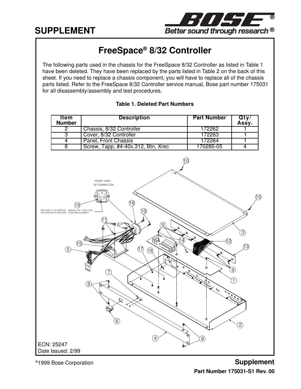
Page 1
Table 2. Current Part Numbers
Part List Notes:
1. This part is not normally available from Customer Service. Approval from the Field Service
Manager is required before ordering.
2. The individual parts located on the PCBs are listed in the Electrical Part List.
3. This part is critical for safety purposes. Failure to use a substitute part with the same safety
characteristics as the recommended replacement part might create shock, fire and/or other
hazards.
Note: If you are replacing the PCB Assembly (item 1), you must also order heatsinks (item 11)
as the PCB is not supplied with them. The heatsinks clip onto the voltage regulators
in the positions shown in the drawing below.
5X10
76X
11
1 4X
92X
8
4
3
2 5
FRONT VIEW
OF CONNECTOR
120V USE ONLY WITH
250V FUSE
SEE PAGE 11 OF SERVICE MANUAL P/N: 175031 FOR VOLTAGE SELECTION AND FUSE REPLACEMENT
View A
View A
6
14
12
13
Item
NumberDescriptionPart NumberQty/
Assy.Note
1 PCB Assy, 8/32 Controller179089 1 1, 2
2 Chassis, 8/32 Controller 187967-001 1 1
3 Cover, 8/32 Controller 198374-002 1
4 Transformer, 110V/240V 173681 1 3
5 Switch, Power, Rocker, SPST143960 1 3
6 Lens, LED, Clear, Chassis144023 2
7 Screw, Mach, 4-40x.25, PAN, XREC 103140-04 6
8 Screw, Tapp, 4-40x.375, PAN, XREC 170284-06 2
9 Nut, Hex, 8-32, Keps 118260-08 2
10 Screw, 6-32, Mach, Flat, Xrec 198422-008 5
11 Clip, Heatsink188599 2
12 Screw, Tapp, 4-24, Type AB186881-04 3
13 Insulator, Chassis, 8/32 Controller 176146 1 1, 3
14 Tape, Foam, 0.50 198408 2