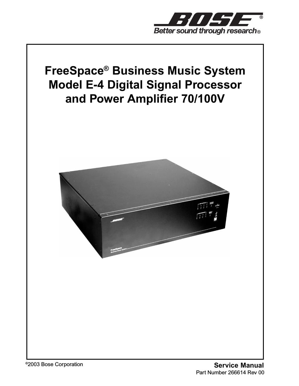
Page 1
1
PROPRIETARY INFORMATION
THIS DOCUMENT CONTAINS PROPRIETARY INFORMATION OF
BOSE ® CORPORATION WHICH IS BEING FURNISHED ONLY FOR
THE PURPOSE OF SERVICING THE IDENTIFIED BOSE PRODUCT
BY AN AUTHORIZED BOSE SERVICE CENTER OR OWNER OF THE
BOSE PRODUCT, AND SHALL NOT BE REPRODUCED OR USED FOR
ANY OTHER PURPOSE.
Contents
Safety Information ............................................................................................................. ................ 2
Electrostatic Discharge Sensitive (ESDS) ...................................................................................... 3
Device Handling ................................................................................................................ ................ 3
Warranty Information ........................................................................................................... ............. 3
Specifications ................................................................................................................. ............... 4-9
Theory of Operation ............................................................................................................ ...... 10-16
Disassembly/Assembly Procedures ....................................................................................... 17-19
Figure 1. Amp PCB and Heat Sink Assembly ................................................................................. 19
Te s t P r o c e d u r e S e t u p . . . . . . . . . . . . . . . . . . . . . . . . . . . . . . . . . . . . . . . . . . . . . . . . . . . . . . . . . . . . . . . . . . . . . . . . . . . . . . . . . . . . . . . . . . . . . . . . . . . . . . . . . . . .......... 20
Te s t P r o c e d u r e s . . . . . . . . . . . . . . . . . . . . . . . . . . . . . . . . . . . . . . . . . . . . . . . . . . . . . . . . . . . . . . . . . . . . . . . . . . . . . . . . . . . . . . . . . . . . . . . . . . . . . . . . . . . . . . . . ........ 21-23
Par t List Notes ................................................................................................................ ................. 24
Figure 2. E-4 Exploded View .................................................................................................... ....... 25
Main Part List ................................................................................................................. ................. 26
Electrical Part List ........................................................................................................... .......... 27-60
Packaging Part List ............................................................................................................ ............. 61
Figure 3. Packaging Exploded View .............................................................................................. ..61
IC Pin Out Diagrams ............................................................................................................ ..... 62-68
Appendix ....................................................................................................................... ............. 69-72
Page 2
2
SAFETY INFORMATION
1. Par ts that have special safety character istics are identified by the symbol on schemat-
ics or by special notes on the parts list. Use only replacement parts that have critical character-
istics recommended by the manufacturer.
2. Make leakage current or resistance measurements to determine that exposed parts are
acceptably insulated from the supply circuit before returning the unit to the customer.
Use the following checks to perform these measurements:
A. Leakage Current Hot Check -With the unit completely reassembled, plug the AC line cord
directly into a 120V AC outlet. (Do not use an isolation transformer during this test.) Use a
leakage current tester or a metering system that complies with American National Standards
Institute (ANSI) C101.1 "Leakage Current for Appliances" and Underwriters Laboratories (UL)
6500 / IEC 60056 paragraph 9.1.1. With the unit AC switch first in the ON position and then in
OFF position, measure from a known earth ground (metal water pipe, conduit, etc.) to all
exposed metal par ts of the unit (antennas, handle bracket, metal cabinet, screwheads, metallic
overlays, control shafts, etc.), especially any exposed metal par ts that offer an electrical return
path to the chassis. Any current measured must not exceed 0.5 milliamp. Reverse the unit
power cord plug in the outlet and repeat test. ANY MEASUREMENTS NOT WITHIN THE
LIMITS SPECIFIED HEREIN INDICATE A POTENTIAL SHOCK HAZARD THAT MUST BE
ELIMINATED BEFORE RETURNING THE UNIT TO THE CUSTOMER.
B. Insulation Resistance Test Cold Check -(1) Unplug the power supply and connect a
jumper wire between the two prongs of the plug. (2) Turn on the power switch of the unit. (3)
Measure the resistance with an ohmmeter between the jumpered AC plug and each exposed
metallic cabinet part on the unit. When testing 3 wire products, the resistance measured to the
product enclosure should be between 2 and infinite MOhms. Also, the resistance measured to
exposed input/output connectors should be between 4 and infinite MOhms. When testing 2
wire products, the resistance measured to exposed input/output connectors should be between
4 and infinite M Ohms. When testing 2 wire products, the resistance measured to exposed
input/output connectors should be between 4 and infinite M Ohms.
If it is not within the limits specified, there is the possibility of a shock hazard, and the unit must
be repaired and rechecked before it is returned to the customer.
CAUTION --DANGER OF EXPLOSION IF BATTERY IS INCORRECTLY REPLACED OR
MISTREATED. REPLACE ONLY WITH THE SAME OR EQUIVALENT TYPE. DO NOT RE-
CHARGE, DISASSEMBLE OR DISPOSE OF IN FIRE.
Replace battery with Panasonic part number BR2325 only. Use of another battery
may present a risk of fire or explosion.