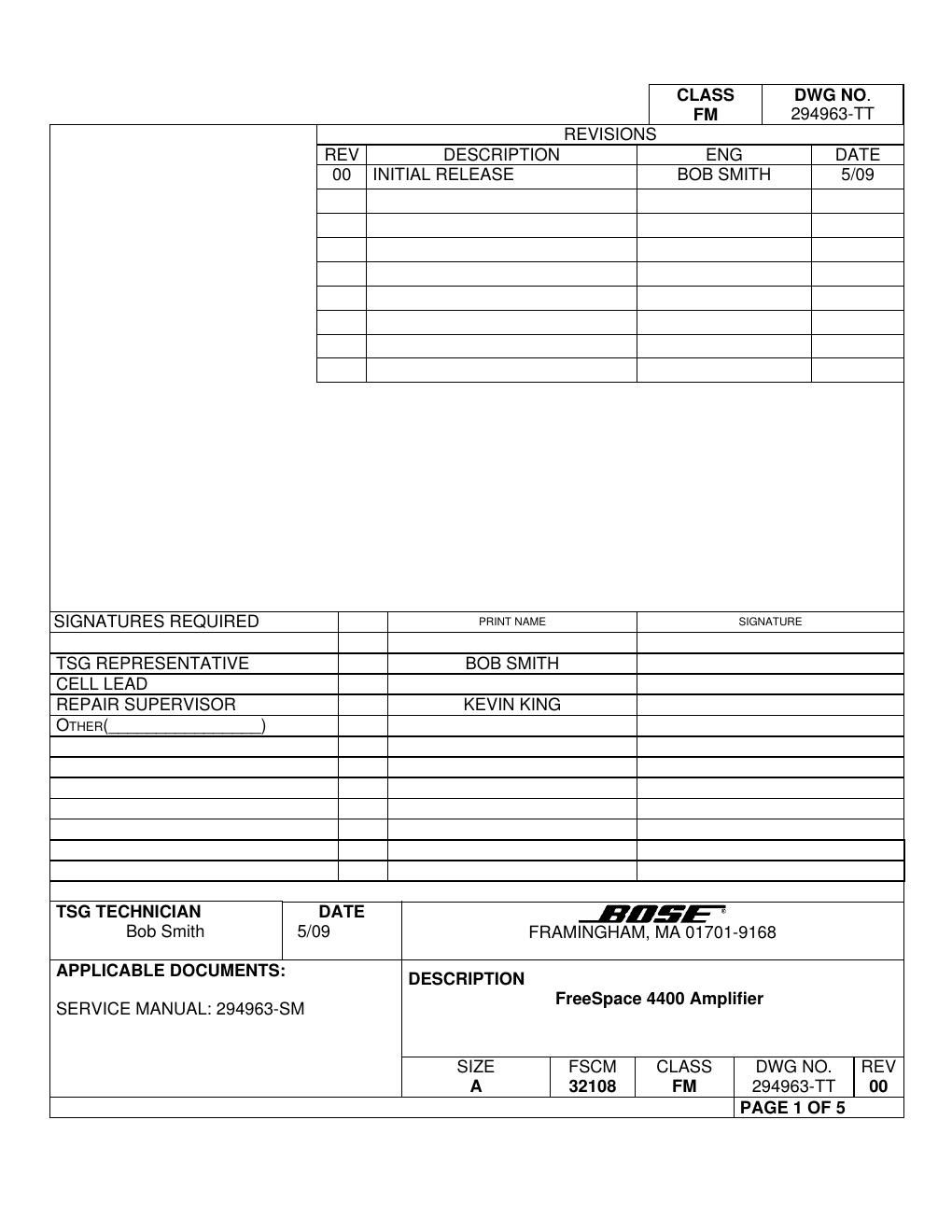
Bose freespace 4400 amplifier 294963 troubleshooting rev00 fs4400 amp

This is the 5 pages manual for bose freespace 4400 amplifier 294963 troubleshooting rev00 fs4400 amp.
Read or download the pdf for free. If you want to contribute, please mail your pdfs to info@audioservicemanuals.com.

Page: 1 / 5
left right
bose freespace 4400 amplifier 294963 troubleshooting rev00 fs4400 amp

Extracted text from bose freespace 4400 amplifier 294963 troubleshooting rev00 fs4400 amp (Ocr-read)


Page 2

Framingham, MA 01701-9168 SIZE A FSCM 32108 CLASS FM DWG NO. 294963-TT SHEET 3 of 5 REV. 00 Product Symptom Check Action FreeSpace ® 4400 amplifier System STATUS LED is lit red Error log and system wiring 1. Switch the system to STANDBY and then back to active again. If the SYSTEM STATUS LED is green, the system may have logged an error. Check the error log on the unit using the FS 4400 Installer software. 2. Switch the system to STANDBY. Set the power switch on the rear panel to OFF. Wait for the STANDBY indicator to turn off. Set the power switch to ON. Press the STANDBY switch and check to see if the SYSTEM STATUS LED is now green. 3. Switch the system to STANDBY. Set the power switch on the rear panel to OFF. Disconnect all input and output signal cables. Set the power switch to ON. Press the STANDBY switch. Reconnect one cable at a time and check the SYSTEM STATUS LED and the error log to see if there are errors. FreeSpace 4400 amplifier System STATUS LED is lit red Error log for power-on self test failure The power-on self test (POST) checks five major hardware components. Connect to the system using the FreeSpace Installer software to view the error log messages. The failures types are below. 1. Host controller -“ will cause the message Power- on self test incomplete to appear in the host controller test section of the error log. This is usually caused by a SRAM address failure. 2. Flash memory -“ Contains the system configuration, design file and the system event schedule. Error log will have an entry Power-on self test incomplete in the host controller flash test section. 3. Peripheral controller -“ This monitors contact closures, rear panel connections and user interface connections. Error log will have an entry Power-on self test incomplete in the peripheral controller flash test section of the error log. Check the user interface wiring for shorts or a failed keypad. 4. DSP -“ The DSP performs all signal processing and routing functions. Error log will have an entry Power-on self test incomplete in the DSP test section of the error log. 5. Upper and lower amplifier -“ Amplifier channels 1 and 2 are located on the upper amplifier board. Channels 3 and 4 are located on the lower amplifier board. The upper and lower amplifier test determines if the amplifiers are working properly. Error log will have an entry Power-on self test incomplete in the upper or lower amplifier test section of the error log.