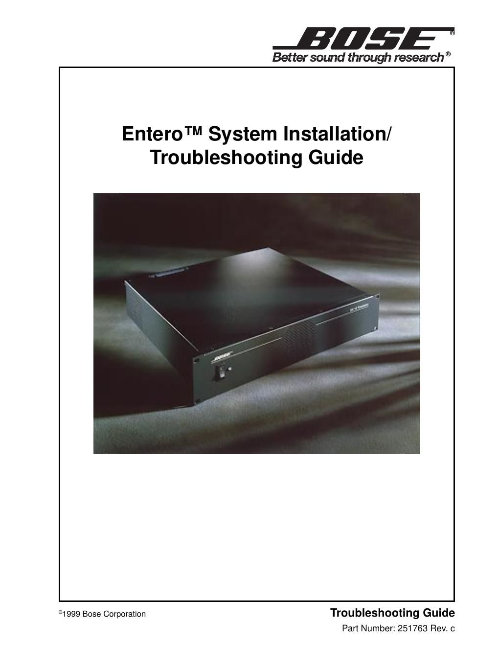
Bose entero installation troubleshooting guide

This is the 57 pages manual for bose entero installation troubleshooting guide.
Read or download the pdf for free. If you want to contribute, please mail your pdfs to info@audioservicemanuals.com.

Page: 1 / 57
left right
bose entero installation troubleshooting guide

Extracted text from bose entero installation troubleshooting guide (Ocr-read)


Page 1

2 Audience .................................. 3 Safety Information ......................... 4 Electrostatic Discharge Sensitive (ESDS) Device Handling ............. 4 Enteroª System Installation Flow Chart ...................... 5 Entero System Troubleshooting Flow Chart ....................... 6 Entero Computer Related Problems Troubleshooting Flow Chart .............. 7 Entero Network Troubleshooting Flow Chart ..................... 8 Entero Hardware Troubleshooting Flow Chart ........................... 9 Section 1: PCC-10 Laptop PC Network Adapter Card Information ................. 10-19 Figure 1.1. PCC-10 Card Network Port Connector (not to scale) ..............18 Figure 1.2. PCC-10 Card Network Cable Connector (not to scale) ..............18 Figure 1.3. PCC-10 Card Network Port Electrical Interface ..................19 Table 1.1. PCC-10 Network Port Electric Interface Description .................19 Section 2: PCNSI Desktop PC Network Adapter Interface Card Information ..... 20-27 Figure 2.1 PCNSI Card Mechanical Layout and Interfaces ........................20 Table 2.1 PCNSI Card Interfaces .............................................20 Table 2.2 SMX-Compatible Transceivers ....................................21 Figure 2.2 Setting the PCNSI Base Address with switch S1 ....................22 Figure 2.3 PCNSI Default Base Address Setting .................................22 Table 2.3 Typical I/O Address Usage in PC-Compatibles ........................22 Table 2.4 Typical Interrupt Request Usage in PC-Compatibles ......................24 Section 3: FTT-10A Network Information ..................................... 28-33 Figure 3.1 Block Diagram of a LonWorks ¨ Device on a Twisted-Pair Network .........28 Figure 3.2 FFT-10A Free Topology Network Diagram ....................................29 Table 3.1 Cable Types and Typical Parameters ................................30 Table 3.2 Free Topology Network Specifications ................................31 Section 4: Echelon ¨ Model 71000 Router Information .............................. 34-41 Figure 4.1 Sample Router Installation ............................................34 Figure 4.2 Router Assembly Using the Router Core Module .............................35 Figure 4.3 Echelon Model 71000 Router Diagram ...................................36 Table 4.1 Model 71000 Router Interfaces .......................................37 Figure 4.4. RJ-45 Connector Pin-out Diagram ....................................38 Figure 4.5 Network Termination Circuits for TP/XF and TP/RS485 Networks .................39 Table 4.2 Power Supply Characteristics ..........................................40 Figure 4.6 Model 71000 Routing Mounting Bracket Fabrication Diagram ..............41 Section 5. K11 and K12 Keypad Information .................................... 42-46 Figure 5.1 K11 and K12 Keypads for Entero System ...................................42 Figure 5.2 K12 Keypad and Cover .................................................43 Figure 5.3 K11 and K12 Keypad Base Module Front View (without keypad) ..................45 Figure 5.4 K11 and K12 Keypad Schematic Diagram .........................................46 Section 6: Junction Box and Wiring Guidelines ....................................... 47 Figure 6.1 Typical Topology for 78kbps, 1.25Mbps, and RS-485 Networks ...................47 Figure 6.2 Typical Network Topology for Free Topology Networks .......................48 Figure 6.3 Stub Junction Box Wiring Diagram ...........................................49 Figure 6.4 Local Loop Terminal Junction Box Diagram .........................................50 Section 7: SE-16 Audio Processor Disassembly/Assembly Procedures ............ 51 Section 8: General Troubleshooting ............................................... 52 Service LED Behavior .............................................................. 52-53 Figure 8.1 Service LED Behavior Diagram ................................................52 Section 8: General Troubleshooting ............................................................ 53 Section 9: Reference Information .................................................... 54-56 CONTENTS

Page 2

3 CAUTION: The components listed in this Installation/Troubleshooting Guide contain no user-serviceable parts. To prevent warranty infractions, refer servicing to warranty service centers or factory service. AUDIENCE This Installation/Troubleshooting Guide is intended for anyone who is installing, maintaining, or troubleshooting a Bose ¨ Enteroª System; as well as an aid for instructors setting up a training course on the Entero System. It contains information about the various components that make up an Echelon ¨ LonWorks ¨ network as they pertain to the Bose Entero System. This includes computer setup information; Echelon Network Interface Card information; network wiring, router, and junction box information; and flow charts to direct you to the appropriate service manual for Bose hardware. It is not intended to be a definitive answer to any and all problems that can be encountered when using an Entero system. It is intended to help point you in the direction where you can find answers to your installation and troubleshooting problems. Note: Your Entero System as installed may or may not include some of the items as described in this document. PROPRIETARY INFORMATION THIS DOCUMENT CONTAINS PROPRIETARY INFORMATION OF BOSE ¨ CORPORATION WHICH IS BEING FURNISHED ONLY FOR THE PURPOSE OF SERVICING THE IDENTIFIED BOSE PRODUCT BY AN AUTHORIZED BOSE SERVICE CENTER AND SHALL NOT BE REPRODUCED OR USED FOR ANY OTHER PURPOSE.