Bose cinema system controller manual

This is the 17 pages manual for bose cinema system controller manual.
Read or download the pdf for free. If you want to contribute, please mail your pdfs to info@audioservicemanuals.com.

Page: 1 / 17
left right
bose cinema system controller manual

Extracted text from bose cinema system controller manual (Ocr-read)


Page 1

JUSE

Bettersoundtivoughresearch
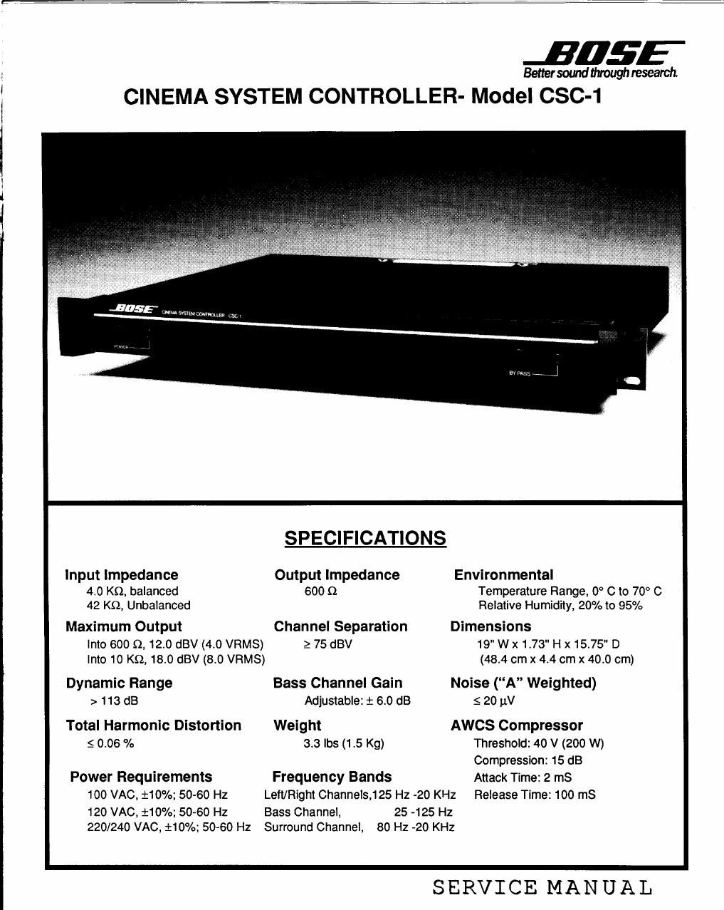
CINEMA SYSTEM CONTROLLER- Model CSC-1

admin «:3: ,

SPECIFICATIONS

Input Impedance Output Impedance Environmental
4.0 KG, balanced 600 (2 Temperature Range. 0° c to 70° c
42 K9,, Unbalanced Relative Humidity, 20% to 95%
Maximum Output Channel Separation Dimensions
Into 600 (2, 12.0 dBV (4.0 VRMS) 2 75 dBV 19" w x 1.73" H x 15.7 " D
Into 10 K9, 18.0 dBV (8.0 VRMS) (48.4 cm x 4.4 cm x 40.0 cm)

Dynamic Range Bass Channel Gain Noise (A Weighted)
> 113 dB Adjustable: : 6.0 dB 5 20 11V

Total Harmonic Distortion Weight AWCS Compressor
s 0.06 % 3.3 lbs (1.5 Kg) Threshold: 40 v (200 W)
Compression: 15 dB
Power Requirements Frequency Bands Attack Time: 2 m8
100 VAC, 110%; 50-60 Hz Left/Right Channels,125 Hz -20 KHz Release Time: 100 m8
120 VAC, 110%; 50-60 Hz Bass Channel, 25 -125 Hz
220/240 VAC, i10%; 5060 Hz Surround Channel, 80 Hz -20 KHz

SERVICE MANUAL

Page 2

HE F P RATI N

The Bose® Cinema System Controller (CSC-1) is a multi-channel, active equalizer for use in 35 mm
Dolby® Stereo movie theaters. The CSC-1 is a part of the Bose Wave System which also includes; the Bose
802T, 1021 and Acoustic Wave® Cannon (AWCS) loudspeakers.-

The CSC-1 consists of 5 input channels. The left, right and center channels are high-pass filtered,
compensated for screen loss and equalized for reproduction through the 802's. The surround channel is
equalized for reproduction through the 102s.

The Bass channel is derived from the summation of the bass, left, right and center channels. This
summed signal is band-pass filtered from 28 Hz to 125 Hz and then equalized for reproduction through the
Acoustic Wave Cannon System.

Because of variances in speaker placement, number of speakers and acoustic loading between movie
houses, the CSC-1 permits matching of the bass channel output to the front channel output by means of a rear
panel gain control.

The AWCS driver is protected by a feedback limiting circuit which monitors the amplifier output and turns
on when the 40 Volt (200 W) threshold is exceeded. >

An emergency, straight-wire bypass switch is provided. The switch will bypass every channel function in
the controller and direct the input to the center channel output only.

NOTE: Attempt to recreate the customer's problem and note any discrepancies with the specifications given in
the test procedure.

TEST PROCEDURE

Necessary Equipment: Signal (sine wave) Generator, Oscilloscope, Distortion Analyzer Man "A" weighted
filter, and a Voltmeter.
Note: If the distortion analyzer does not have an "A" weighted filter an external filter is needed.

Gain Test:

1. Connect the CSC-1 as in Fig 1.

2. Adjust the frequency of the signal generator to 750 Hz.

3. Adjust the output level of the signal generator to 0.775 VRMS.
4. Measure the gain at the left channel output.

Output: 0.8 VRMS 10.2 VRMS.

Repeat steps (1 to 4) for the right and center channels.
Connect the signal generator to the bass channel input.
Adjust the frequency of the signal generator to 30 Hz.
Adjust the output level of the signal generator to 100 mV.
Turn the AWCS level adjust fully clockwise.

0. Measure the gain at the bass channel output.

Output: 2 750 mV.

PPNPF