Bose amplus 50 100 194101 b1

This is the 4 pages manual for bose amplus 50 100 194101 b1.
Read or download the pdf for free. If you want to contribute, please mail your pdfs to info@audioservicemanuals.com.

Page: 1 / 4
left right
bose amplus 50 100 194101 b1

Extracted text from bose amplus 50 100 194101 b1 (Ocr-read)


Page 1

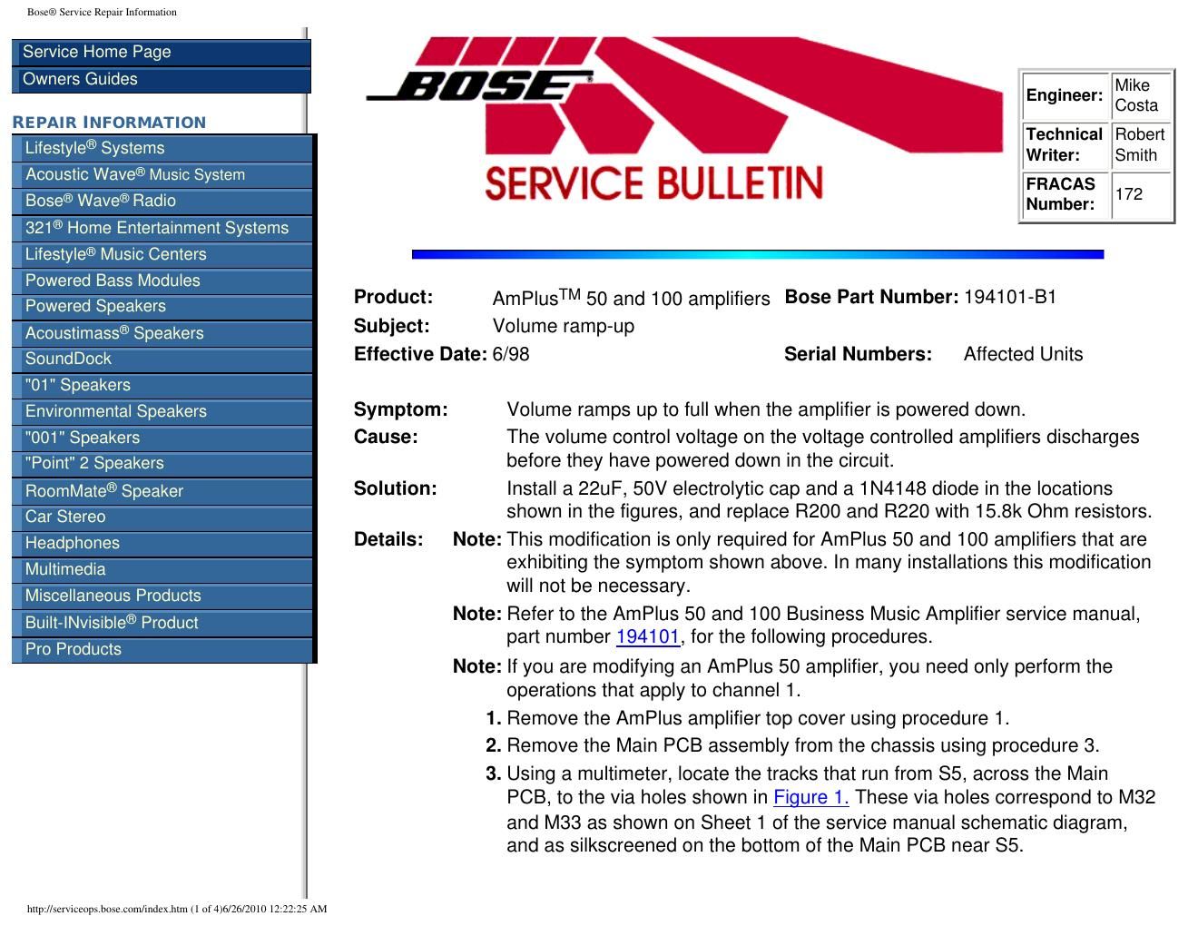
Bose® Service Repair Information 4.Remove the solder in the via holes shown, so that you can install the ca\ p leads through them. 5. Using an Exacto TM knife, cut the trace on the bottom of the PCB that runs between the via hole to M33 and the main portion of the trace (see Figure 2). Be sure to leave the portion of the trace that runs to R200 intact. Ver\ ify that the trace is open using the multimeter. 6. Cut the trace that runs from the via hole to M32 and the collector of Q2\ 21 (see Figure 2). Be sure to leave the portion of the trace that runs to R220 intact. Verify that the trace is open using the meter. 7.Install the 22uF, 50V caps (Bose P/N: 137126-220) into the locations shown. Be sure that the negative lead is installed into the via hole for\ M32 or M33 as applicable. 8.Pre-form the 1N4148 diode (Bose P/N: 121501) leads as shown in Figure 2, and solder them in place as shown. 9. Replace R200 and R220 with 15.8k Ohm resistors (Bose P/N: 133625- 1582). This is to keep the loading on the circuitry the same as before \ modification. 10. Replace the Main PCB assembly into the amplifier chassis using procedure\ 4. 11.Replace the AmPlus amplifier top cover using procedure 2. http://serviceops.bose.com/index.htm (2 of 4)6/26/2010 12:22:25 AM

Page 2

Bose® Service Repair Information Figure 1. AmPlus Amplifier Topside Etch and Component Layout Diagram Return to Text http://serviceops.bose.com/index.htm (3 of 4)6/26/2010 12:22:25 AM