Bose am 7 service

This is the 20 pages manual for bose am 7 service.
Read or download the pdf for free. If you want to contribute, please mail your pdfs to info@audioservicemanuals.com.

Page: 1 / 20
left right
bose am 7 service

Extracted text from bose am 7 service (Ocr-read)


Page 1

JU5E

Bettersoundlhroughresearch.
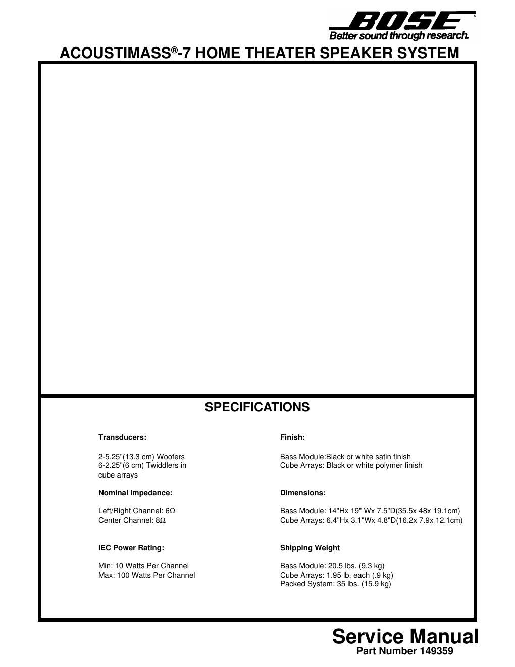
ACOUSTIMASS®-7 HOME THEATER SPEAKER SYSTEM

SPECIFICATIONS

Transducers: Finish:

2-5.25"(13.3 cm) Woofers Bass Module:Black or white satin finish
6-2.25"(6 cm) Twiddlers in Cube Arrays: Black or white polymer finish
cube arrays

Nominal Impedance: Dimensions:

Left/Flight Channel: 69 Bass Module: 14"Hx 19" Wx 7.5"D(35.5>< 48x 19.1cm)
Center Channel: 89 Cube Arrays: 6.4"Hx 3.1"Wx 4.8"D(16.2x 7.9x 12.1cm)
IEC Power Rating: Shipping Weight

Min: 10 Watts Per Channel Bass Module: 20.5 lbs. (9.3 kg)

Max: 100 Watts Per Channel Cube Arrays: 1.95 lb. each (.9 kg)
Packed System: 35 lbs. (15.9 kg)

Service Manual

Part Number 149359

Page 2

PROPRIETARY INFORMATION

This document contains proprietary information of BOSE® Corporation which is being
furnished only for the purpose of servicing the identified BOSE product by an authorized
BOSE service center or owner of the BOSE product, and shall not be reproduced or used
for any other purpose.

BOSE ®ACOUSTIMASS®-7 (AM-7) TECHNICAL DESCRIPTION

The system consists of three cube arrays and a bass module. The arrays contain the same
2-1/4" shielded twiddlersTM as the Acoustimass-5 Series II. Magnetic shielding allows
placement of the arrays near TV sets. By rotating one cube, the mid and high frequency
pattern can be tailored to the listeners preference. The bass module has two

5-1/4", unshielded woofers. It can be hidden anywhere and provides multi-directional bass.

TEST PROCEDURES

NOTES: Some of the test procedures require the user to access the woofers and /or
twiddlers. Refer to the Disassembly/Assembly Procedures section for specific
instructions.

Use the test setup in Figure 1 unless otherwise specified.
System Level Test Procedures
1. Woofer Rub and Tick Test

NOTE: This test applies to the left and right channels only. The woofers are not connected
to the center channel of the bass module.

Connect a sine wave oscillator to a power amplifier. Adjust the frequency of the oscillator to
10 Hz and the amplifier output to 10 Vrms. Connect the amplifier output to the left and
right channel input terminals on the AM-7 bass module (see Figure 1). No extraneous
noises such as rubbing, scraping or ticking should be heard.

NOTE: To distinguish between normal suspension noise or rub and ticks, remove the
terminal cap panel and displace the cone on each woofer slightly with your fingers. If the
noise can be made to go away or get worse, it is a rub or a tick and the woofer should be
replaced. If the noise stays the same, it is normal suspension noise and the woofer is fine.
Suspension noises will not be heard with program material.