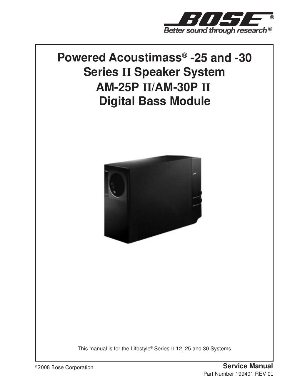
Bose am 25p ii am 30p ii 199401 service manual

This is the 54 pages manual for bose am 25p ii am 30p ii 199401 service manual.
Read or download the pdf for free. If you want to contribute, please mail your pdfs to info@audioservicemanuals.com.

Page: 1 / 54
left right
bose am 25p ii am 30p ii 199401 service manual

Extracted text from bose am 25p ii am 30p ii 199401 service manual (Ocr-read)


Page 1

Contents Warranty Period ................................................................................................................................ 1 Safety Information ............................................................................................................................ 2 Electrostatic Discharge Sensitive (ESDS) Device Handling ........................................................ 3 Specifications ................................................................................................................................... 4 Theory of Operation .................................................................................................................... 5-17 Figure 1. DSP PCB Block Diagram ................................................................................................17 Figure 2. DSP Signal Flow .............................................................................................................17 Disassembly/Assembly Procedures ....................................................................................... 18-22 Figure 3. Top Cover Screw Location ..............................................................................................18 Figure 4. Cover Latch Rotated Out ................................................................................................18 Figure 5. Cover Latch Rotated In ...................................................................................................18 Figure 6. Base Plate Tabs ..............................................................................................................18 Figure 7. Amplifier Assembly ..........................................................................................................20 Figure 8. Woofer Harness Hookup .................................................................................................21 Test Set-up Parameters and Equipment ...................................................................................... 23 Test Procedures ........................................................................................................................ 24-25 Part List Notes ................................................................................................................................ 26 Main Parts List ................................................................................................................................ 27 Figure 9. Bass Box and Module Exploded Views ..........................................................................28 Electrical Part List ..................................................................................................................... 29-41 Satellite Part List ............................................................................................................................ 42 Figure 10. LS12/25 Satellite Assembly ..........................................................................................42 Figure 11. LS30 Jewel Cube ¨ Assembly ........................................................................................42 LS12 II Packaging Part List ........................................................................................................... 43 Figure 12. LS12 II Packaging View ................................................................................................43 LS25 II Packaging Part List ........................................................................................................... 44 Figure 13. LS25 II Packaging View ................................................................................................44 LS30 II Packaging Part List ........................................................................................................... 45 Figure 14. LS30 II Packaging View ................................................................................................45 Accessory Part List ........................................................................................................................ 46 Figure 15. Accessory Kit View ........................................................................................................47 Integrated Circuits .................................................................................................................... 48-51 CAUTION: THE BOSE ¨ AM-25P AND AM-30P SERIES II BASS MODULES CONTAIN NO USER-SERVICEABLE PARTS. TO PREVENT WARRANTY INFRACTIONS, REFER SER- VICE TO WARRANTY SERVICE STATIONS OR FACTORY SERVICE. The Bose Lifestyle ¨ 12, 25 and 30 Series II Speaker Systems are covered by a limited 1-year transferable warranty. WARRANTY PERIOD

Page 2

2 SAFETY INFORMATION 1. Parts that have special safety characteristics are identified by the symbol on schematics or by special notes on the parts list. Use only replacement parts that have critical characteristics recommended by the manufacturer. 2. Make leakage current or resistance measurements to determine that exposed parts are acceptably insulated from the supply circuit before returning the unit to the customer. Use the following checks to perform these measurements: A. Leakage Current Hot Check-With the unit completely reassembled, plug the AC line cord directly into a 120V AC outlet. (Do not use an isolation transformer during this test.) Use a leakage current tester or a metering system that complies with American National Standards Institute (ANSI) C101.1 ÒLeakage Current for AppliancesÓ and Underwriters Laboratories (UL) 1492 (71). With the unit AC switch first in the ON position, then in the OFF position, measure from a known earth ground (metal water pipe, conduit, etc.) to all exposed metal parts of the unit (antennas, handle bracket, metal cabinet, screw heads, metallic overlays, control shafts, etc.), especially any exposed metal parts that offer an electrical return path to the chassis. Any current measured must not exceed 0.5 milliamp. Reverse the unit power cord plug in the outlet and repeat test. ANY MEASUREMENTS NOT WITHIN THE LIMITS SPECIFIED HEREIN INDICATE A POTENTIAL SHOCK HAZ- ARD THAT MUST BE ELIMINATED BEFORE RETURNING THE UNIT TO THE CUSTOMER. B. Insulation Resistance Test Cold Check-(1) Unplug the power supply and connect a jumper wire between the two prongs of the plug. (2) Turn on the power switch of the unit. (3) Measure the resistance with an ohmmeter be- tween the jumpered AC plug and each exposed metallic cabinet part on the unit. When the exposed metallic part has a return path to the chassis, the reading should be between 1 and 5.2 Megohms. When there is no return path to the chassis, the reading must be ÒinfiniteÓ. If it is not within the limits specified, there is the possibility of a shock hazard, and the unit must be repaired and re- checked before it is returned to the customer. PROPRIETARY INFORMATION THIS DOCUMENT CONTAINS PROPRIETARY INFORMATION OF BOSE ¨ CORPORATION WHICH IS BEING FURNISHED ONLY FOR THE PURPOSE OF SERVICING THE IDENTIFIED BOSE PRODUCT BY AN AUTHORIZED BOSE SERVICE CENTER OR OWNER OF THE BOSE PRODUCT, AND SHALL NOT BE REPRODUCED OR USED FOR ANY OTHER PURPOSE.