Bose 4x4 series ii schematics

This is the 9 pages manual for bose 4x4 series ii schematics.
Read or download the pdf for free. If you want to contribute, please mail your pdfs to info@audioservicemanuals.com.

Page: 1 / 9
left right
bose 4x4 series ii schematics

Extracted text from bose 4x4 series ii schematics (Ocr-read)


Page 1

1 3 4 5 6 7 8 9 10 11
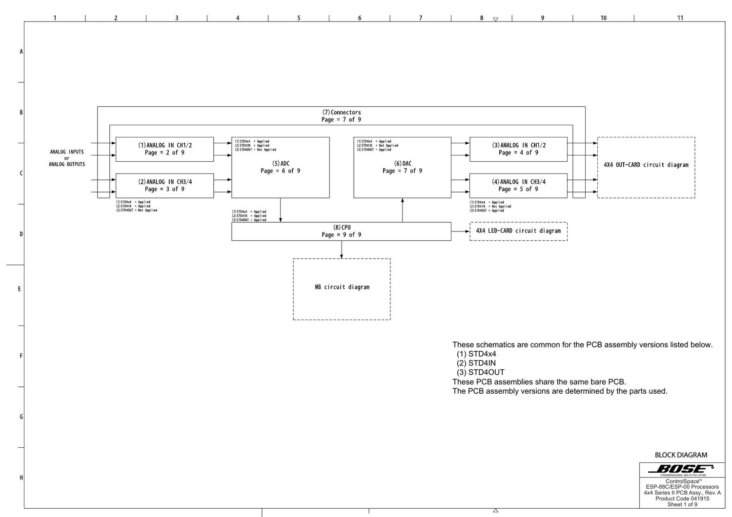
(7)Connectors
Page = 7 of 9
, , I 777777777777777777777777
(1)ANALOG IN CH1/2 ' 111213271 £21115: 81213371 :léiliéna ' (3)ANALOG IN CH1/2 '; l
ANALOG INPUTS Page = 2 of 9 (3)5Tu4uui=~ox Applied (3)5TD4DUT=Applied Page = 4 of 9 I :
or |
ANALOG OUTPUTS (5)ADC (6)DAC 5 4X4 OUT-CARD circuit diagram 1
Page=6of9 Page=7of9 i 1
(2)ANALOG IN CH3/4 (4)ANALOG IN (H3/4 : i
Page = 3 of 9 Page = S of 9 _1 :
I J
(1)51D4x4 =Applied (1)5TD4x4 :Applied -
(2)51D41N = Applied (ZJSTMIN = Not Applied
(3)5m40ur : Not Applied (mm f W M (sismaur : Applled
812132111 : 211111123 ________________________
(8)CPU 1 _ . , . 1
Page = 9 of 9 Hi 4X4 LED CARD mrcurt diagram i
i 77777777777 i 77777777777 1
l |
l |
1 :
1 MB circuit diagram 5
l |
l |
l |
1 :
l. _______________________ 1

These schematics are common for the PCB assembly versions listed below.

(1) STD4x4
(2) STD4|N
(3) STD4OUT
These PCB assemblies share the same bare PCB.

The PCB assembly versions are determined by the parts used.

BLOCK DIAGRAM

JHSE

FRAMINGHAM MAHiTUl-Siea

ControlSpaCeTM
ESP-88C/ESP-00 Processors
4x4 Series II PCB Assy., Rev. A
Product Code 041915
Sheet 1 of 9