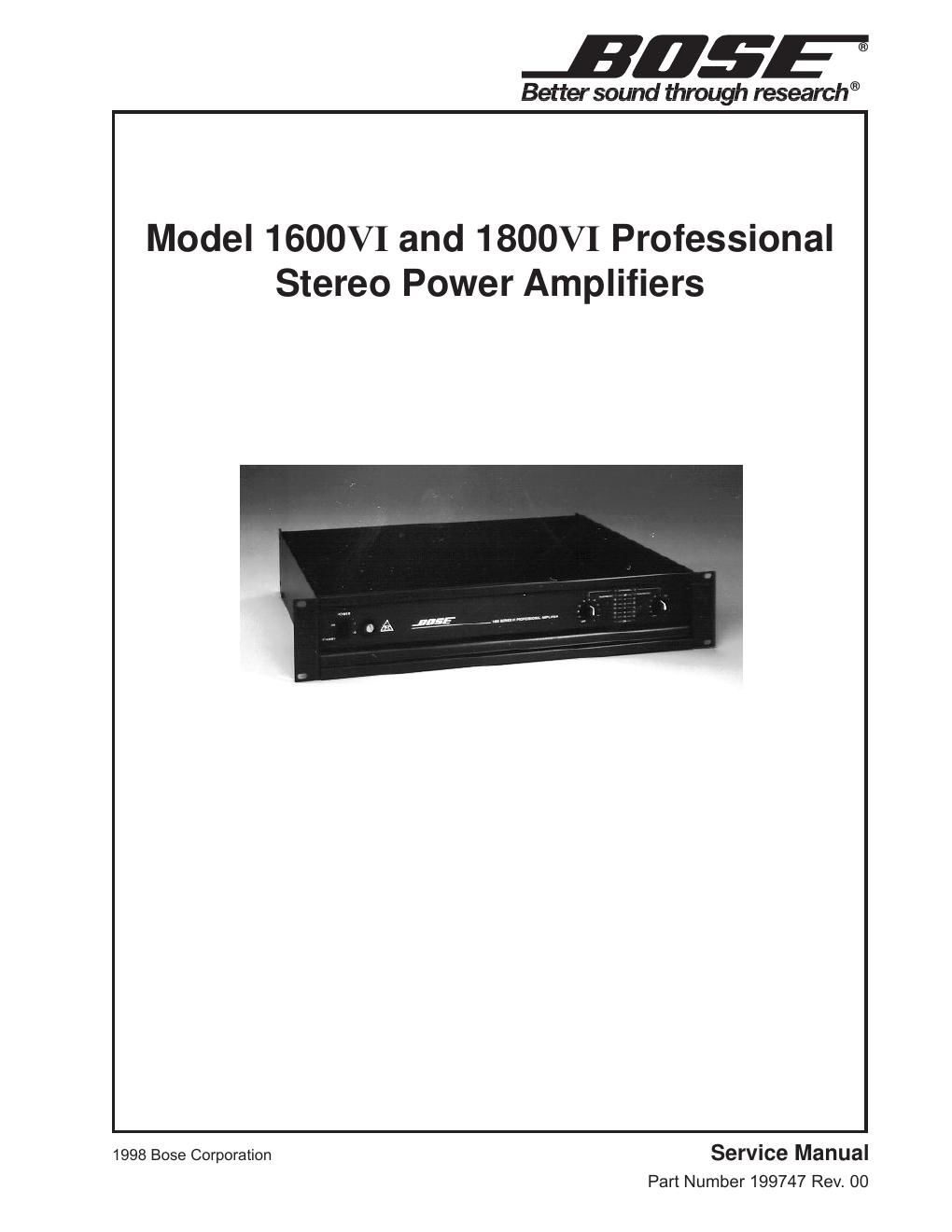
Bose 1800 vi pwr service manual

This is the 60 pages manual for bose 1800 vi pwr service manual.
Read or download the pdf for free. If you want to contribute, please mail your pdfs to info@audioservicemanuals.com.

Page: 1 / 60
left right
bose 1800 vi pwr service manual

Extracted text from bose 1800 vi pwr service manual (Ocr-read)


Page 1

JEEP

Better sound through research®

Model 1600VI and 1800VI Professional
Stereo Power Amplifiers

1998 Bose Corporation Service Manual
Part Number 199747 Rev. 00

Page 2

CONTENTS

Safety Information ............................................................................................................................ 4
Electrostatic Discharge Sensitive (ESDS) Device Handling . .. 4
1800VI Specifications ........................................................ 5-6
1600VI Specifications ....................... 7-8
Figure 1. 1600VI and 1800VI Block Diagram .................................................................................. 9
Theory of Operation .................................................................................................................. 10-18
Disassembly/Assembly Procedures .. 19-30
Figure 2. Cover Removal Screw Location Side View ..................................................................... 19
Figure 3. Cover Attaching Hardware .............................................................................................. 20
Figure 4. Rear View - Attaching Hardware .. 20
Figure 5. 240V Configuration ......................................................................................................... 21
Figure 6. 1600Vl and 1800V1 Amplifier Assembly ......................................................................... 21
Figure 7. Bottom Mounted Components ................... 22
Figure 8. Side View- Bottom Mounted Components 27
Figure 9. Heatsink Bridge ................... .. 27
Figure 10. Input Module Screw Location .29
Test Procedures ................................ .. 31 -33

Figure 11. EQ Card Placement
Frequency Response Test Table

.. 31
32


Part List Notes ............................. 34
Main Part List ..... 35-37
Figure 12. Amplifier Test Setup Diagram ....................................................................................... 31
Figure 13. Front Panel Views, 100V and 120V Variation, 240V Variation .. 37
Figure 14. Back Panel View ........................................................................................................... 37
Figure 15. Cross Section View ....................................................................................................... 38
Figure 16. 1600Vl and 1800VI Amplifier Top View ...................... 39
Figure 17. 1600Vl and 1800VI, Amplifier Assembly Removed View .. 40
Electrical Part List .. 41-54
Packing List .................................... .. 55
Figure 18. 1600V1 and 1800VIAmp|ifiers Packing Diagram. 55
Wiring Diagrams ............................................. .. 56-57
Figure 19. 1600V1 and 1800VI Wiring Iagram ........ 56
Figure 20. 1600Vl and 18OOVI 240V Wiring Diagram. .57
IC Pinout Diagrams ................................................................................................................... 58-59