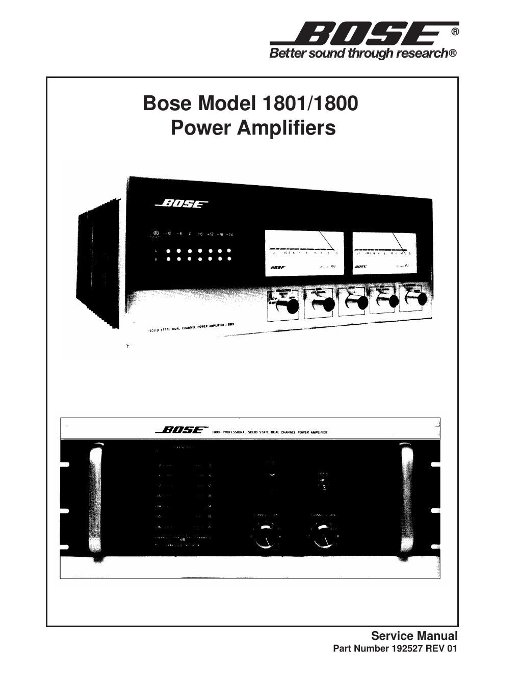
This is the 32 pages manual for bose 1800 1801 service.
Read or download the pdf for free.
If you want to contribute, please mail your pdfs to info@audioservicemanuals.com.
£055
Better sound through research®
Bose Model 1801/1800
Power Amplifiers
JHEE' mwmmm sum mm M mm m. umnu
Service Manual
Part Number 192527 REV 01
Contents
Specifications ................................................................................................................................... 2
Safety Information .................
Electrostatic Discharge Sensitive (ESDS) Device Handling ........................................................ 4
Disassemny/Assembly Procedures .................................... .. 5-8
Test Procedures ............................................................................................................................... 9
Figure 1. 1801 Component Location .............................................................................................. 10
Figure 2. 1801 Side View ................ .. 10
11
11
11
.. 12
Figure 3. 1800 Front Panel ....................
Figure 4. 1800 Rear View of Front Panel ..
Figure 5. 1801 Rear View of Front Panel ..
Figure 6. 1800 Rear Panel ..................... .
Figure 7. 1801 Rear Panel ............................................................................................................. 12
Part List Notes ................................................................................................................................ 13
Figure 8. 1801 Front Panel 13
Part List ...................................................................................................................................... 14-17
Figure 9. 1801/1800 Block Diagram ............................................................................................... 18
Figure 10. LED PCB Layout ................... 19
Figure 11. LED PCB Schematic Diagram ...................................................................................... 20
Figure 12. Amplifier Schematic Diagram ........................................................................................ 21
Figure 13. Amplifier PCB Layout ........ 22
Troubleshooting Guide ................ 23
Voltage Conversion Instructions 24
Service Bulletin ......................................................................................................................... 25-28