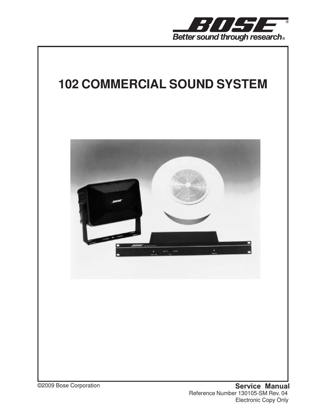
Bose 102 commercial sound system manual rev4

This is the 29 pages manual for bose 102 commercial sound system manual rev4.
Read or download the pdf for free. If you want to contribute, please mail your pdfs to info@audioservicemanuals.com.

Page: 1 / 29
left right
bose 102 commercial sound system manual rev4

Extracted text from bose 102 commercial sound system manual rev4 (Ocr-read)


Page 1

Electrostatic Discharge Sensitive (ESDS) Device Handling..............\ ...........................................3 Safety Information......................................................\ ..........................................................................4 Specifications..........................................................\ .............................................................................5 Disassembly/Assembly Procedures ........................................\ ..................................................... 6 -9 102 ® Flush-Mount Loudspeaker........................................................................\ ............................... .6 Figure 1. 102 Flush-Mount Grille Removal................................\ ....................................................... ......6 Figure 2. 102 Flush-Mount Driver Replacement............................\ ....................................................... .6 102 Surface-Mount Loudspeaker........................................................................\ .......................... ....7 Figure 3. 102 Surface-Mount Driver Removal/Replacement..................\ ..............................................7 Figure 4. 102 Surface-Mount Baffle Assembly........................................................................\ ............ ..8 102 System Controller Procedures........................................\ ....................................................... .8-9 Figure 5. 102 System Controller Exploded View........................................................................\ .......... 10 Figure 6. 102 System Controller Block Diagram ..........................\ ......................................................11 Test Procedures .........................................................\ ................................................................ 12-15 Figure 7. Test Connections for 102F or 102S Loudspeaker................................................................ 12 102 Loudspeaker Test Signals.............................................................\ ...................................... ......12 102 System Controller Test Procedures .........................................................\ ............................. 13 102 System Controller Initial Switch Positions..........................\ ....................................................13 102 System Controller Frequency Response................................\ ................................................14 102 System Controller Test Procedures..........................................................\ .........................14-15 102 System Controller Voice Channel Response...................................................\ .......................15 102 Loudspeaker Driver Wiring ..........................................\ ....................................................... .....16 Figure 8. 102 Loudspeaker Schematic Diagram (Passive Units)...........\ ............................................ 16 Figure 9. 102 Loudspeaker Schematic Diagram (Transformer Units)................................................ 16 Figure 10. Tap Selection Switch Wiring (Transformer Units).............................................................. 16 Tap Selection Switch Wiring..............................................\ ...................................................... ........16 102 Flush-Mount Loudspeaker Parts List (Per Figure 10) ...............\ .......................................... 17 102 Flush-Mount Loudspeaker Installation Hardware ......................\ .......................................... 17 102 Loudspeaker Exploded Views .........................................\ ....................................................... 18 Figure 11a. 102 Flush-Mount Non-RoHS Loudspeaker Exploded View............................................ .. 18 Figure 11b. 102 Flush-Mount RoHS Loudspeaker Exploded View...................................................... 18 102 Surface-Mount Loudspeaker Parts List (Per Figures 11 & 12) ........................................... 19 102 Surface-Mount Loudspeaker Installation Hardware ....................\ ........................................ 19 Figure 12. 102 Surface-Mount Loudspeaker Exploded View............................................................... 20 Figure 13. 102 Surface-Mount Loudspeaker ..............................\ ....................................................... 21 102 System Controller Parts Lists ......................................\ ...................................................... 22-25 102 System Controller Packing List .....................................\ ......................................................... 25 102 Loudspeaker Packing Diagrams .......................................\ ................................................. 26-27 Figure 14. 102 Flush-Mount Loudspeaker Packing Diagram..................\ ............................................ 26 Figure 15. 102 Surface-Mount Loudspeaker Packing Diagram................\ ........................................... 27 Service Manual Revision History........................................................................\ ........................ .....28 CONTENTS 2

Page 2

3 PROPRIETARY INFORMATION THIS DOCUMENT CONTAINS PROPRIETARY INFORMATION OF BOSE ¨ CORPORATION WHICH IS BEING FURNISHED ONLY FOR THE PURPOSE OF SERVICING THE IDENTIFIED BOSE PRODUCT BY AN AUTHORIZED BOSE SERVICE CENTER OR OWNER OF THE BOSE PRODUCT, AND SHALL NOT BE REPRODUCED OR USED FOR ANY OTHER PURPOSE. CAUTION: THE 102 ¨ SYSTEM CONTROLLER CONTAINS NO USER-SERVICEABLE PARTS. TO PREVENT WARRANTY INFRACTIONS, REFER SERVICING TO WARRANTY SERVICE STATIONS OR FACTORY SERVICE. ELECTROSTATIC DISCHARGE SENSITIVE (ESDS) DEVICE HANDLING This unit contains E SDS devices. We recommend the following precautions when repairing, replacing, or transporting ESDS devices: - Perform work at an electrically grounded work station. - Wear wrist straps that connect to the station or heel straps that connec\ t to conductive floor mats. - Avoid touching the leads or contacts of ESDS devices or PC boards even i\ f properly grounded. Handle boards by the edges only. - Transport or store ESDS devices in ESD protective bags, bins, or totes. \ Do not insert unprotected devices into materials such as plastic, polystyrene foam, cl\ ear plastic bags, bubble wrap, or plastic trays.