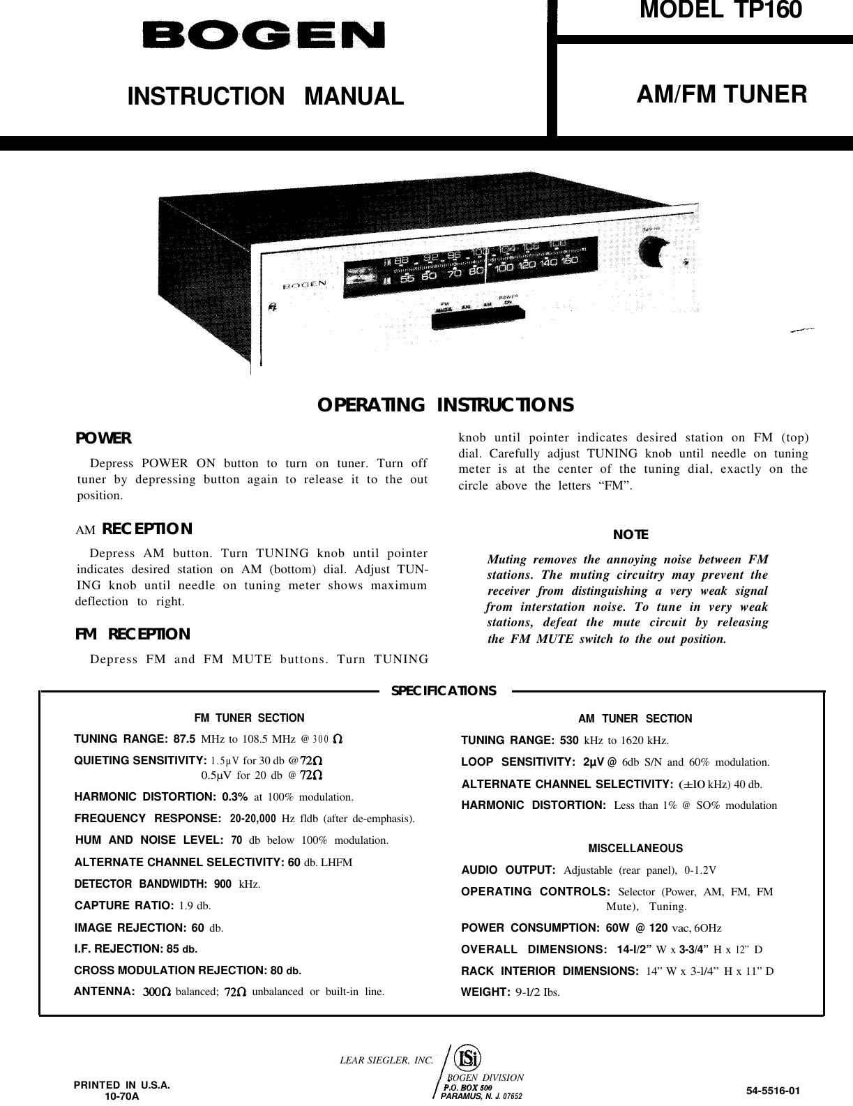
Bogen TP 160 Owners Manual

This is the 10 pages manual for Bogen TP 160 Owners Manual.
Read or download the pdf for free. If you want to contribute, please mail your pdfs to info@audioservicemanuals.com.

Page: 1 / 10
left right
Bogen TP 160 Owners Manual

Extracted text from Bogen TP 160 Owners Manual (Ocr-read)


Page 1

BOGEN

INSTRUCTION MANUAL

fang-mu!

3

MODEL TP160

AM/FM TUNER


OPERATING INSIRUC'I'IONS

POVIER

Depress POWER ON button to turn on tuner. Turn off
tuner by depressing button again to release it to the out
position.

AM REC EP'IION

Depress AM button. Turn TUNING knob until pointer
indicates desired station on AM (bottom) dial. Adjust TUNr
ING knob until needle on tuning meter shows maximum
deflection to right.

FM REZEPIION
Depress FM and FM MUTE buttons. Turn TUNING

FM TUNER SECTION
TUNING RANGE: 87.5 MHz to 1085 MHz @ 300 n

QUIETING SENSITIVITY: 1.5m fol3U db @720
0.5pv for 20 db @ 720

HARMONIC DISTORTION: 0.3% at 100% modulation.
FREQUENCY RESPONSE: 2040.000 Hz tldb (after de-emphasis).
HUM AND NOISE LEVEL: 70 db below 100% modulation.
ALTERNATE CHANNEL SELECTIVITY: 60 db. LHFM

DETECTOR BANDWIDTH: 900 kHz.

CAPTURE RATIO: 1.9 db.

IMAGE REJECTION: 60 db.

I.F. REJECTION: 85 db.

CROSS MODULATION REJECTION: 80 db.

ANTENNA: 3000 balanced; 720 unbalanced or built-in line.

SPECIHCA110NS

knob until pointer indicates desired station on FM (top)
dial. Carefully adjust TUNING knob until needle on tuning
meter is at the center of the tuning dial, exactly on the
circle above the letters FM".

NOTE

Muting removes the amulying noise between FM
stations. The muting circuitry may prevent the
receiver from distinguishing a very weak signal
from interstatitm noise. T0 tune in very weak
statiuns, defeat the mute circuit by releasing
the FM MUTE switch to the out position.

AM TUNER SECTION
TUNING RANGE: 530 kHz to 1620 kHz.
LOOP SENSITIVITY: 2|.IV@ 6:11: S/N and 60% modulation.
ALTERNATE CHANNEL SELECTIVITY: (:10 kHz) 40 db.
HARMONIC DISTORTION: Less than 1% @ 80% modulation

MISCELLANEOUS
AUDIO OUTPUT: Adjustable (rear panel). 0-1.2V

OPERATING CONTROLS: Selector (Power. AM, FM. FM
Mute), Tuning.

POWER CONSUMPTION: 60W @120 vac,6OHz
OVERALL DIMENSIONS: 14-1/ " W x 3-3/4" H x 12 D
RACK INTERIOR DIMENSIONS: 14 W x 3-1/4" H x 11"D
WEIGHT: 9-1/21bs.

LEAR SIEGLER, INC.

OGEN DIVISION
PRINTED IN u.s.A. psomxm

10-7DA PAHAMUS. N. J 07552 54'5516'01

Page 2

INSTALLATION INSTRUCTIONS

UNPACKING

NOTE

This paragraph dues not apply to tuners shipped
as a part Ufa Bogen Centralized School Sound Sys-
tern console or rack.

If the Model TP160 AM/FM Tuner is not part of a Bogen
Centralized School Sound System console or rack, care,
fully unpack the carton and inspect the unit for damage.
If a unit shipped to you proves to be damaged, make an
immediate claim with the shipping carrier. If the unit was
picked up directly from a dealer or distributor, make any
damage claim directly to the seller without delay.

RACK INSTALLATION

NOTE

This paragraph applies only to tuners which will
be installed in a 19equipment rack.

The Model TP160 may be installed in a standard 19 equip,
ment rack by using Model RPK31 rack mounting brackets.
Remove the four screws securing the side of the cover.
D11 not remove the cover. Install the brackets as shown
in figure I. securing them to the tuner with the four screws
supplied with the brackets. Each bracket has two elongated
holes on threeiinch centers for fastening to a standard 19
equipment rack.

CONNECTING AM ANTENNA

An external antenna must be installed on any Model
TPIbO which will be used to receive AM broadcasts. Con,
nect the antenna as shown in figure 2.

CONNECTING EXTERNAL FM ANTENNA
IMPORTANT

Always disconnect the FM Line Antenna
when using an external FM antenna.

The Model TPIbO has an internal FM Line Antenna which
may be used for receiving FM broadcasts. For improved
reception, particularly in weak signal areas or for tuners
mounted in consoles or racks, installation of an outdoor FM
or T" antenna is necessary. If you are installing a standard
ZOOrohm antenna system, connect the twinilead transmission
line as shown in figure 3a. lf conditions require use of a
coaxial transmission line, such as RGill/U or RG759/U,
connect the cable as shown in figure 3b. Coaxial cable must
be used when the transmission line is run in conduit.

Figure 1 - Rack Mounting With Model RPK-31 Brackets

l74-l730-0l

r-3I:)~(I)n-1
@ooo
AM GN D

Figure 2 - Connecting AM Antenna

Connecting To External TV Antenna

For optimum performance. a separate FM antenna is rec,
ommended. if a TV antenna must be used for both FM and
TV reception, install an FM signal splitter at the end of the
transmission line, as shown in figure 4.

LEVEL CONTROL

Model TP160 AM/FM tuners shipped with Bogen Ceni
tralized School Sound System consoles or racks have the
LEVEL control preset to the proper output for the booster
amplifier. Tuners shipped separately have the LEVEL con,
trol set for maximum output, which is 1.2 volts.

To decrease the audio output from the tuner, turn the
LEVEL control counterclockwise. To increase the audio
output, turn the LEVEL control clockwise.