Bogen NDB250 Operating Manual

This is the 9 pages manual for Bogen NDB250 Operating Manual.
Read or download the pdf for free. If you want to contribute, please mail your pdfs to info@audioservicemanuals.com.

Page: 1 / 9
left right
Bogen NDB250 Operating Manual

Extracted text from Bogen NDB250 Operating Manual (Ocr-read)


Page 1

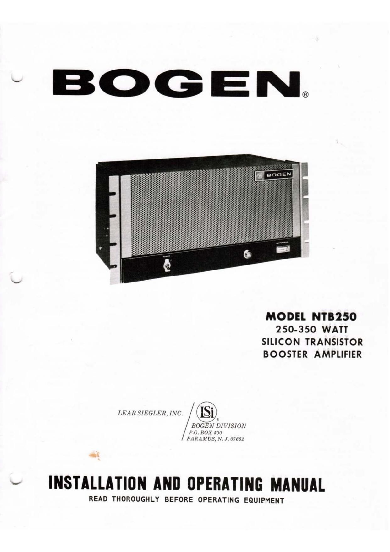
MODEL NTB250
250-350 WATT
SILICON TRANSISTOR
BOOSTER AMPLIFIER

LEAR SIEGIER. INC.

BOGEN DIVISION
PX), BOX 54m
PAHAJIL'S,NHL/1755:

l

INSTALLATION ANII OPERATING MANUAL

READ THOROUGHLY BEFORE OPERATING EQUIPMENT

Page 9

NEMOVAILE ASSEMBLIES

The Electronic Component Board Assembly and
the Output Stage Assembly may be readily removed from
the chassis to facilitate servicing as shown in figure 6.
The component board IS detached by removing five
Phillips head screws which fasten it to the mounting
plate and disconnecting the push-in wire plugs. The
output stage, consisting of the output transrstors mount-
ed on an extrudable aluminum heat sink. is detached
from the chassis by removing the four Phillips head
screws on the heat sink and then unplugging the
assembly.

CAUTION
There are no user serviceable parts in the: Chris
sis. and no replacement or rt-pnir shr-uld bn
attempted except by u qualifit'tl sun-ire
technician.

FUSE REPLACEMENT

In addition to the 10-ampere circuit breaker for
the ac power line, a 40-arnpere cartridge fuse is located
on the top chassis to protect the dc lines (see figure 1).
This fuse should be replaced only with a 40-amp AGU
or SAG fuse.

The output lines are also protected by two 20-
unpere fuses located on the rear panel and shown in
figure 1. These fuses should be replaced with 20-amp

AGU or SAG fuses only. Unscrew the fuse cap and
remove the fuse from the holder.

PILOT LIBN'I'

The poweron indicator light on the front panel
utilizes a long-life bulb, which will seldom require re
placement. If it should burn out, however, it may be
easily replaced. Unscrew the lens on on the front
panel (see figure 6) and remove the lamp. Replace with
a 6.3vvolt .050 amp miniature lamp, (3.15. 1302.

TRANSISTORS

Transistors show little, if any, deterioration with
age and, at the present time, are considerably more
reliable than the best vacuum tubes. Therefore, some
transistors are soldered into equipment like resistors
or capacitors. If the set is inoperative, it generally is
safe to assume that these transistors have not failed
and that the trouble is elsewhere in the equipment.

However, if previous tests indicate that a transis-
tor might be faulty, it must be removed from the circuit
for checking. The plug-in transistors in the output state
can be easily replaced after detaching the output stage
assembly as described above. After removing defective
transistor. brush a silicon grease compound such as
Dow Corning No. 340 on the heat sink and transistor.
Make certain that no foreign matter remains on heat
sink or transistor. To insure proper contact, screw
down plug-in transistors tightly.

RIPLACIMINT PARTS

The components used in Bogen equipment. with
exception of items listed below, are standard parts
available through most parts jobbers. However, several

parts should be replaced only with genuine Bogen parts.

These parts are listed here and are available through
Bogen distributors, service agencies or directly from
the factory.

Ref. No. Part No. Description
C101 79-108-(DZ Capacitor, 32,000uF. 30V.
105C
CR101, 102 96-5246-01 Diode. Silicon Rectifier
CR103 96-5118-02 Diode. 15 PIV. 30 ma
CR104 965109-02 Diode, 150 PIV, 100 the
F101 94-0006-06 Fuse. 40 A. 32 V
F102, 103 94-0006-04 Fuse. 20 A. 32 V
1101 94-0222-01 Lamp, Power Indicator
R101 77-001-605 Volume Control, 100 K 9
R123 76-121-002 Resistor. 2.5 Q, 10 W
T101 83-740-000 Transformer, Power
T102 83-372-010 Transformer, Output
T103 83-372-020 Transformer. Output
85-0147-02 Plug, Remote Standby &
Volume
85-0109-01 Plug, Polarized, 120 V
Output

70-9166-01 Link, Output Terminal Strip
ELECTRONIC COMPONENT BOARD ASSEMBLY
Part No. 45-96844)!
79-504~040 Capacitor, Tantalum 4.7uF.
20V

C6, 7

When ordering a part, specify part number and de-
scription of the part as listed below. Specify the model
and give the series designation, which is a run letter
followed by numbers, stamped or screened on the rear
of the chassis. Also, give the component board assem-
bly number (45-) for all parts mounted on PC boards.
For reference designations, see the schematic diagram,
figure 6.

Ref. No. Port No. Description

C10 79-504-048 Capacitor, Tantalum, lOuF,
10 V

C14 79-508-002 Capacitor, Tantalum, 100uF,
3 V

C15, 17 79-106-003 Capacitor, Electrolytic,
2000nF, 25 V

CR1-4. 6, 7 96-5242-01 Diode, Stabistor. Silicon

CR5 96-5124-02 Diode, Xener, 6.8 V

CR8 96-5138-02 Diode, Zener, 12 V

CR9 96-5109-02 Diode, Silicon 150 PIV

01. 7, 8, 9 95.522901 Transistor. BC149C

02A, 28,4, 5 96-5213-01 Transistor, 2N5089
03. 6, 10, 11 966244-01 Transistor, 2N5183
012, I3 96-5245-01 Transistor, 2N5497
R42 76-121-001 Resrstor. 1509. 10 W

OUTPUT STAGE ASSY., PART NO. 454689-01

0101-116 96-5247-01 Transistor
or
96-5285-0l
R101-116 76-113-098 Resistor. 0.22 (I. 5 W

-9-