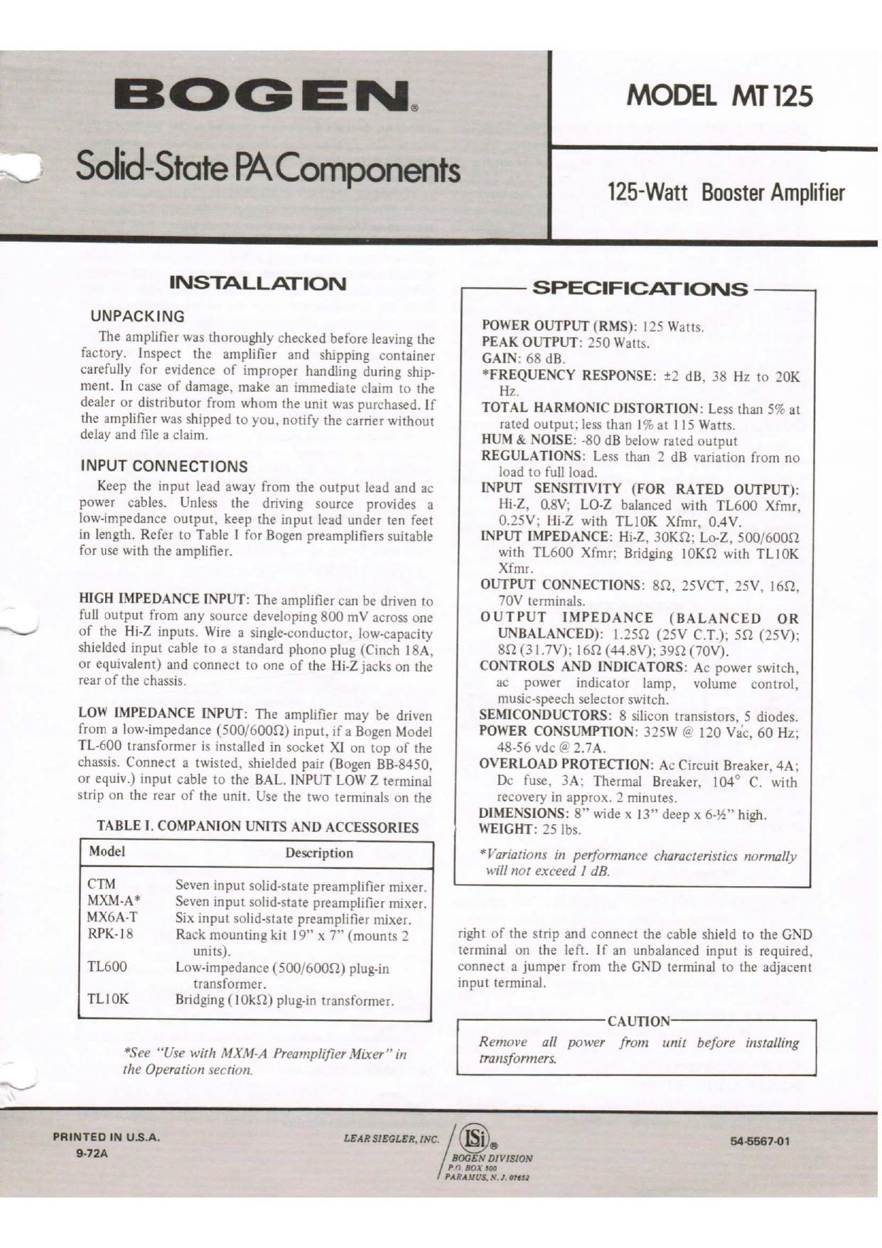
Bogen MT125 Operating Manual

This is the 4 pages manual for Bogen MT125 Operating Manual.
Read or download the pdf for free. If you want to contribute, please mail your pdfs to info@audioservicemanuals.com.

Page: 1 / 4
left right
Bogen MT125 Operating Manual

Extracted text from Bogen MT125 Operating Manual (Ocr-read)


Page 1

V Solid-State BAComponenis

.\_y

INSTALLATION

UNPACKING

The amplifier was thoroughly checked before leaving the
factory, Inspect the amplifier and shipping container
carefully for evidence of improper handling during ship-
ment. In case of damage. make an immediate claim to the
dealer or distributor from whom the unit was purchased. If
the amplifier was shipped to you. notify the carrier without
delay and file a claim.

INPUT CONNECTIONS

Keep the input lead away from the output lead and ac
power cables. Unless the driving source provides a
low-impedance output. keep the input lead under ten feet
in length. Refer to Table I for Bogen preamplifiers suitable
for use with the amplifier.

HIGH IMPEDANCE INPUT: The amplifier can be driven to
full output from any source developing 800 mV across one
of the Hi-Z inputs. Wire a single-conductor. low-capacity
shielded input cable to a standard phono plug (Cinch 18A.
or equivalent) and connect to one of thc Hi-Zjacks on the
rear of the chassis.

LOW IMPEDANCE INPUT: The amplifier may be driven
from a low-impedance (500/6009) input. if a Bogen Model
TL-600 transformer is installed in socket XI on top of the
chassis. Connect a twisted. shielded pair (Bogen 83-8450.
or equiv.) input cable to the BAL. INPUT LOW Z terminal
strip on the rear of the unit. Use the two terminals on the

TABLE I. COMPANION UNITS AND ACCESSORIES

Model Description

CTM Seven input solid-state preamplifier mixer.

MXM-A* Seven input solid-state preamplifier mixer.

MX6A-T Six input solid-state preamplifier mixer.

RPK-IS Rack mounting kit )9 x 7 (mounts 2
units).

TLoOO Low-impedance (500/6009) plug-in
transformer.

TLIOK Bridging ( IOkQ) plug-in transformer.

MODEL MT I25

- SPECIFICATIONS -

POWER OUTPUT (RMS): 125 Watts.

PEAK OUTPUT: 250 Watts.

GAIN: 68 dB.

*FREQUENCY RESPONSE: :2 dB. 38 Hz to 20K
Hz.

TOTAL HARMONIC DISTORTION: Less than 57: at
rated output: less than 17: at 115 Watts.

HUM & NOISE: -80 dB below rated output

REGULATIONS: Less than 3 dB variation from no
load to full load.

INPUT SENSITIVITY (FOR RATED OUTPUT):
Hi-Z. 0.8V: LO-Z balanced with TL6OO Xfmr,
0.35V: Hi-Z with TLIOK Xfmr, 0.4V.

INPUT IMPEDANCE: Hi~Z, BOKQ: Lo»Z. 500/6009
with TLGOO Xtmr: Bridging IOKQ with TLIOK
Xfmr.

OUTPUT CONNECTIONS: 8Q. ZSVCT. 25V. 169.
70V terminals.

OUTPUT IMPEDANCE (BALANCED 0R
UNBALANCED): 1.2552 (25V CT): 59 (25V);
89 (3 I .7V): 16$") (44.8V): 399(70V).

CONTROLS AND INDICATORS: Ac power switch.
ac power indicator lamp. volume control,
music-speech selector switch.

SEMICONDUCTORS: 8 silicon transistors. 5 diodes.

POWER CONSUMPTION: 325W («5 120 Vac. 60 Hz:
4856 vdc @ 2.7A.

OVERLOAD PROTECTION: Ac Circuit Breaker. 4A:
Dc fuse. 3A: Thermal Breaker. 1040 C. with
recovery in approx. 2 minutes.

DIMENSIONS: 8 wide x 13 deep x 6% high.

WEIGHT: 25 lbs.

*Variarions in performance characteristics normally
will not exceed 1 dB.

right of the strip and connect the cable shield to the GND
terminal on the left. If an unbalanced input is required.
connect a jumper from the GND terminal to the adjacent
input terminal.

*See "US? with MXM-A Preamplifier Mixer"in
the Operation section.

CAUTION
Remove all power from unit before installing

transformers.

125-Watt Booster Amplifier

PRINTED IN USA.

072A

LEM 31mm»: 9.
.00 DIVISION

W01

ED. IOX I
PARAIIIII, N. L m

Page 2

BRIDGING INPUT: The inputs for two or more amplifiers
may be paralled without loss of gain. To do this, install a
Bogen Model TL-lOK transformer in socket XI on top of
the chassis. Connect the bridged inputs to BAL LOW Z
terminal strip on the rear ofthe unit. Use the two terminals
on the right of the strip and connect the cable shields to the
GND terminal on the left. If an unbalanced input is
required, connect a jumper from the GND terminal to the
adjacent input terminal.

CONSTANT-VOLTAGE INPUT: The amplifier can be
driven from a standard public address amplifier that
provides a 25-volt or 70-volt constant voltage output. To do
this, connect the output ofthe amplifier to one of the Hi-Z
INPUT jacks via a resistor network (see figure 1). The
resistors shown in figure 1 are in addition to the normal
loudspeaker load on the output of the public address
amplifier.

OUTPUT CONNECTIONS

Speakers may be connected with standard flexible line
cord (zip-cord) and up to 100 feet of cable may be used
without appreciable loss. Class II wiring is acceptable unless
prohibited by local codes.
70V CONSTANT-VOLTAGE OUTPUT. For 70V constant-
voltage operation, connect the speaker leads to the 70V
(399 and COM 2) terminals on the rear of unit. If
grounding is required. connect a jumper from the COM 2 to
GND.

OPERATION

II
IOK
l/ZVI


Ei-
- T0 men

own-r menus:

venom». new or

s-rnw or 0"
DRIVER AWUFIER

74-01304
AT 70V II - IOK. I/ZV

AT 25V RI . 3.3K.l/2W

Figure I - Connection to Constant -
Voltage P.A. Amplifier Driver.

25V CONSTANT-VOLTAGE OUTPUT. For 25V constant-
voltage unbalanced operation, connect the speaker leads to
25V (552) and COM 1, leaving the link connected between
COM 1 and GND. For balanced operation, open the link
between COM 1 and GND. If the output transformer center
tap must be grounded. connect a jumper between ZSVCT
and GND.

16 OHM & 8 OHM OUTPUT. For 169 or 89 operation,
connect the speaker leads between the desired output
terminal and COM 1. If ungrounded operation is desired,
open the link between COM I and GND.

POWER CONNECTIONS.

The booster amplifier may be operated from 120 vac or
48V to 56V dc.

120 VAC SOURCE. Connect the ac power cord to a l20
vac source capable of providing at least 325 watts. Use a
3-wire receptacle with the center pin connected to earth
ground.

If desired, auxiliary equipment may be connected to the
AUX POWER receptacle on top of the unit. Do not draw
more than 380 watts from this receptacle.
48V - 56V DC SOURCE Connect the amplifier to a dc
source capable of delivering at least 2.7 amperes at 48 to 56
volts. To do this, remove the two push-on lugs (Amphenol
42888-1) from the coin envelope packed with the unit.
With the dc supply off, wire the power supply output to
the push-on lugs. Connect the lugs to the dc power
receptacle on the rear of the unit, making certain to observe
proper polarity.

OPERATION
VOLUME CONTROL

A volume control located on the rear of the unit is used
primarily to compensate for variations in preamplifier
output levels. The VOLUME control permits the gain of the
amplifier to be preset so that the preamplifier volume
control may be operated near the center ofits range. rather
than at an extreme maximum or minimum. The VOLUME
control is a screwdriver adjustment which needs to be set
only once for any given preamplifier input.

SETTING FOR MXM-A PREAMPLIFIER. Because of the
high output of the MXM-A, it is important to adjust both
the MXM-A and the booster amplifier properly to avoid
excessive system .gain, hum, noise or possible oscillation.
After installing the equipment, proceed as follows:

a) Rotate the MT125 VOLUME control (on rear of unit) to
approximately '1: turn from the off(fully counterclock-
wise position.

b) Set the MASTER volume control on the MXM-A to 6.
All the preamplifier-mixer channels will now have suf-
ficient sensitivity without providing excessive overall
system gain.

DC POWER OPERATION

When the amplifier is operated from a dc power source,
the ac power switch and ac power indicator lamp will be
inoperative and there will be no power at the AUX POWER
receptacle on top of the chassis. Turn the amplifier on and
off from the power switch on the dc power supply or by
inserting and removing the dc power leads on thenatr of
the unit.

MAINTENANCE

CAUTION
There are no user replaceable parts within the unit.
Have all internal servicing done by a qualified
technician

AC OPERATION

There are two overload protective devices used with ac
operation, the 4A circuit breaker and the temperature
overload thermal breaker.

.2.