Bogen MSK1 Operating Manual

This is the 2 pages manual for Bogen MSK1 Operating Manual.
Read or download the pdf for free. If you want to contribute, please mail your pdfs to info@audioservicemanuals.com.

Page: 1 / 2
left right
Bogen MSK1 Operating Manual

Extracted text from Bogen MSK1 Operating Manual (Ocr-read)


Page 1

MODEL MSK-I
MOIIIIOR SPEAKER

DESCRIPTION

The Bogen Model MSK-l accessory is a monitor
speaker and volume control designed for mounting on
a Bogen amplifier equipped with a speaker grille on
the front panel. The MSK-l accessory makes it possi-
ble to monitor the output level in installations where
the speakers are located at a distance from the ampli-
fier.

The MSK-l may be installed directly into the
Bogen M330A, M60A and M120 amplifiers, as described
below. A five-pin plug, Bogen Part No. 85-0151-01, is
supplied with the accessory for use in mounting the
monitor speaker to the Bogen MTX3OB, MX30A and
MXGOA amplifiers.

INSTALLATION

M33, MOM, M120 AMPLIFIERS

To install the MSK-l monitor speaker and volume
control on the M330A, M60A or M120 amplifier, proceed
as follows:
1. Remove the four corner screws from the bottom of
the amplifier.
2. Remove the top cover enclosure to expose the
amplifier chassis.
3. Remove the sheet metal screw from the bottom
of the chassis. This screw is centered below the
monitor speaker bezel bracket, which is located on
the front panel.
4. Loosen the two nuts which hold the speaker
bezel to the front panel and remove the bracket.
5. Remove the cardboard from behind the speaker
grille.
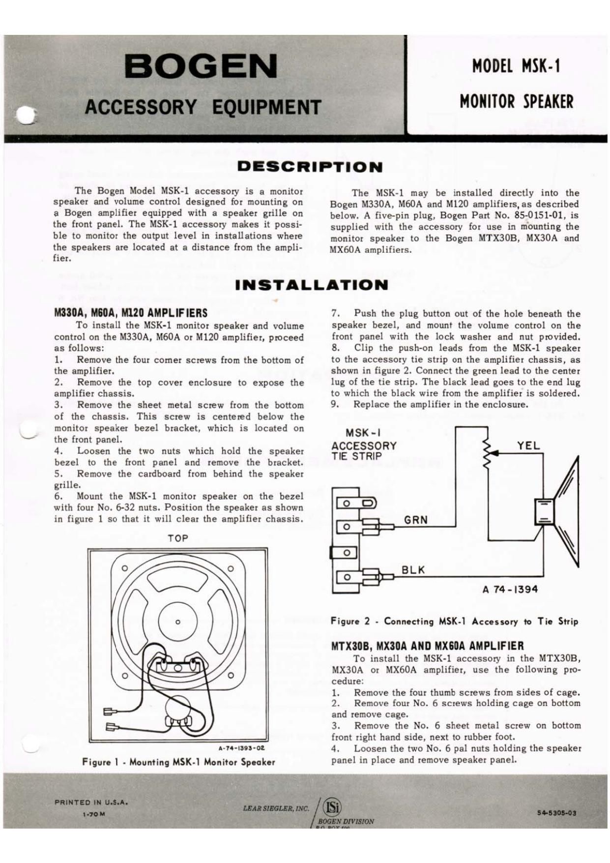
6. Mount the MSK-I monitor speaker on the bezel
with four No. 6-32 nuts. Position the speaker as shown
in figure 1 so that it will clear the amplifier chassis.

TOP

Ado-uu-oe
Figure I - Mounting MSK-l Monitor Speaker

7. Push the plug button out of the hole beneath the
speaker bezel, and mount the volume control on the
front panel with the lock washer and nut provided.
8. Clip the push-on leads from the MSK-l speaker
to the accessory tie strip on the amplifier chassis, as
shown in figure 2. Connect the green lead to the center
lug of the tie strip. The black lead goes to the end lug
to which the black wire from the amplifier is soldered.
9. Replace the amplifier in the enclosure.

MSK-l

ACCESSORY YEL
TIE STRIP

i BLK ,

A 744394

Figure 2 - Connecting MSK-l Accessory to Tie Strip

MTXIIIB. MXIIA AND IIXSIIA AMPLIFIER

To install the MSK-l accessory in the MTXSOB,
MX30A or MX60A amplifier, use the following pro«
cedure:
1. Remove the four thumb screws from sides of cage.
2. Remove four No. 6 screws holding cage on bottom
and remove cage.
3. Remove the No. 6 sheet metal screw on bottom
front right hand side, next to rubber foot.
4. Loosen the two No. 6 pal nuts holding the speaker
panel in place and remove speaker panel.

Page 2

5. Remove the push-on fasteners from the DISK-1
leads, and connect the leads to the five-pin plug
provided with the MSK-l accessory. as shown in

5 pm PLUG figure 3. Solder the green lead to pin 4 of the plug
VIEWED FROM YEL and the black lead to pin 5.
WIRING 8m 6. Remove the cardboard from behind the speaker

grille and push the plug button out of the hole he-

neath the speaker bezel.

7. Mount the monitor speaker behind the bezel using
four No. 6-32 nuts. Position the speaker as shown in

! figure 1 to enable it to clear the amplifier chassis.
8. Mount the volume control on the speaker panel

with the lock washer and nut provided.

9. Replace speaker panel on amplifier front panel.

Replace the two No. 6 psi nuts and tighten.

10. Place S-pin plug into ACCESSORY socket on top

of amplifier dressis and tighten securely.

A 744395 11. Replace and tighten the No. 6 sheet metal screw

on bottom front right-hand side, near the rubber foot.

12. Replace the cage and fasten with the four No. 6

Figure 3 - Connecting SK-l Acuuorr sheet metal screws. Replace leather straps and four
to Five-Pin Plug thumb screws.
0 P I R 11 O N
59* the volume 0 the monk speaker by adjusting amplifier is controlled as described in the instruction
the MSK-l volume control. The output volume of the manual supplied with the amplifier.

REPLACEMENT PARTS

Port No. Description

93-0016-01 Speaker,45-ohm
77-001-569 Control, Volume

OWNERS WARRANTY

Began solid state sound equipment is guaranteed against dalatts in material and workmanship lor one
year item the date at sale to the original purchaser. provnded that the equipment has not been suhiecled
to abuse or accident or altered in any way Any part ol the equipment covered by this warranty which, with
normal installation and use. becomes deiectwa will be repaired or replaced by Hogan. provided the equip
ment is delivered or shipped prepaid and insured to our authorized service station or to the Began Factory
Service Department, Route 4 and Forest Avenue. Paramus, New Jersey 07652 The aguipment may be picked
up by you personally or will he returned to you lreight prapaid

Models containing vacuum tubes carry the same warranty as above, except that it does not apply to the
vacuum tubes, which are guaranteed lot 90 days

Ma "grunt/arr card enclosed mm the lqu/pmalrl muxl be contained and marlad wrlhln Irva day: a! put»
than Io plaza (Ila warranty in ellecl