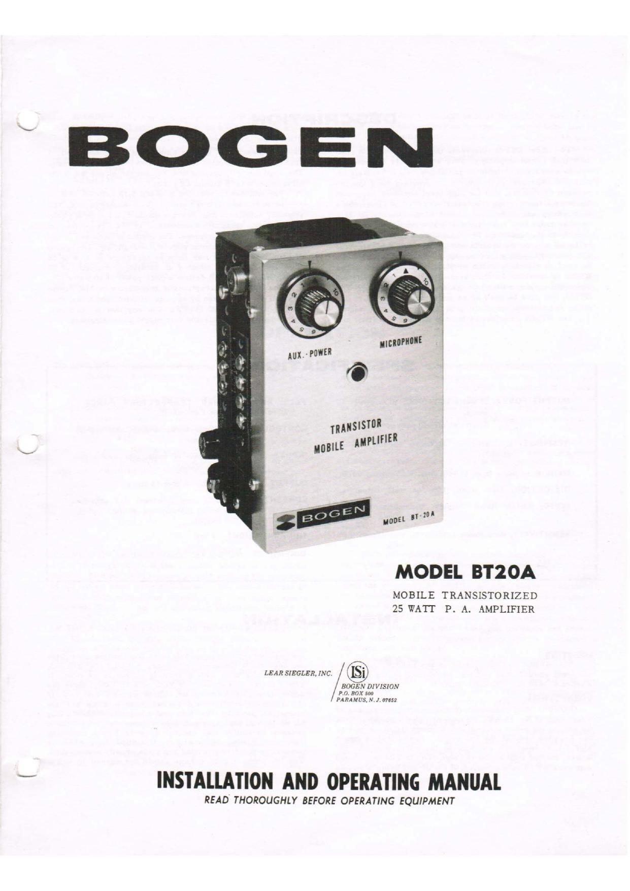
Bogen BT 20 A Operating Manual

This is the 4 pages manual for Bogen BT 20 A Operating Manual.
Read or download the pdf for free. If you want to contribute, please mail your pdfs to info@audioservicemanuals.com.

Page: 1 / 4
left right
Bogen BT 20 A Operating Manual

Extracted text from Bogen BT 20 A Operating Manual (Ocr-read)


Page 1

MODEL BT2 0A

MOBILE TRANSISTORIZED
25 WATT P. A. AMPLIFIER

LEAR SIEGLER, INC. ([5)
BOGEN DIVISION

P 0. BOX 5017
PA RAM vs, .\' 1,0765:

INSTALLATION AND OPERATING MANUAL

READ THOROUGHLY BEFORE OPERATING EQUIPMENT

Page 2

DESCRIPTION

The model BT20A represents the latest design in com-
pact high output amplifiers. This amplifier is intended for
use in mobile and portable public address work. Separate in-
puts and individual gain controls are provided for a low im-
pedance microphone, and for high level auxiliary equipment
(such as a tuner or tape recorder). The BTZOA incorporates
an auxiliary and radio input circuit so that the output of a
two-way radio (any radio for that matter) may be connected
directly to the amplifier. This enables the two-way radio to
be heard outside the vehicle and at considerable distances.
The possible applications are varied (e.g. the amplifier can
be used to distribute music at political rallies, etc.). The
BTZOA is excellent for such applications as police, fire de-
partment, marine, military or general commercial use. The
BT20A may also be used as an emergency standby p.a. am-
plifier in permanent installations in the event of power failure.

The BT20A incorporates builbin RF and line filter cir-

OUTPUT POWER: 25 watts at 14 VDC; peak power 40
watts.
Swatts at 6VDC; peak power 8 watts.

RESPONSE: Optimized for maximum speech intelli-
gibility.

GAIN: Microphone Input llOdb. Aux.-Radio Input 90db.

DISTORTION: Less 10%

NOISE: (Below Rated Output)

than at full output.

Microphone -90 db.
Aux.-Radio -95 db.

SENSITIVITY: Microphone 1 millivolt. Aux.-Radio 0.40
volt.

SPECIFICATIONS

cuits to prevent RF or line noise from being amplified. A
fuse provides protection of the unit from inadvertent shorting.
The amplifier will operate from the battery of any motor ve-
hicle regardless of grounding polarity.

The unit can be operated from any 5-15 volt DC source.
Any battery source such as lantern batteries may beused. The
amplifier supplies a full 25 watts output at a maximum power
supply current drain of 2.9 amperes at 14 VDC. The quiescent
current drain is 0.27 amperes. The frequency response is op-
timized to provide maximum speech intellegibility. The speak-
er used with the unit may have an impedance of 4, 8 or 16
ohms and should be capable of handling a minimum of 25
watts. The BTZOA will deliver a peak power of 40 watts.

The BTZOA is exceptionally temperature stable, opera-
tion will not be affected by extreme climatic conditions; from
-30°C (42°F) to +55C (149°F). The amplifier is compact,
lightweight and portable and very rugged in construction.

FULL RATED POWER TEMPERATURE RANGE:
-22 to + 149 degrees Fahrenheit.

CONTROLS: Aux. Volume/Power Switch, Microphone
Volume.

INPUTS: (2) Microphone (50-500 ohms, 200 ohms nomi-
nal). Auxiliary-Radio.

OUTPUT IMPEDANCE:

CURRENT DRAIN: 0.27 amp quiescent (0.1 amp for
bulb), 2.9 amperes at full rated
output.

SHIPPING WEIGHT: 4 lbs.

4, s or 16 ohms.

DIMENSIONS: 6%" h x 4% w x 4 d.

INSTALLATION

MOUNTING

The BTZOA may be mounted in any position on practi-
cally any surface. The unit may be mounted on the frame of
a vehicle, or to any convenient surface.

CONNECTIONS

POWER: Two conductors (black and red) consisting of
4 feet each of No. 16 AWG wire are provided with the BTZOA
for making the power connections. Connect the black wire to
the negative side of the DC source marked with a minus
sign (-). Connect the red wire to the positive of the DC
source, marked with a plus (+) sign. The BT20A is shipped
with negative (-) side grounded. If the battery being used has

_2_

the positive (4») side grounded, move the shorting strap from
the negative to the positive terminal. A VOLTAGE SELEC-
TOR terminal strip with a shorting jumper is provided. If
power source is between 5-8 VDC or 9-15 VDC,jumper the
appropriate pair of terminals. Check polarity carefully. If
the connecting wires and ground polarity strap are not
connected properly, the fuse and power transistors may
blow. If the fuse blows due to improper polarity, check
polarity carefully, and connect properly before replacing
fuse and turning on amplifier. Operation from either a
positive or negative grounded system is equally permissable.
The DC power supply voltage should not exceed 15 volts.