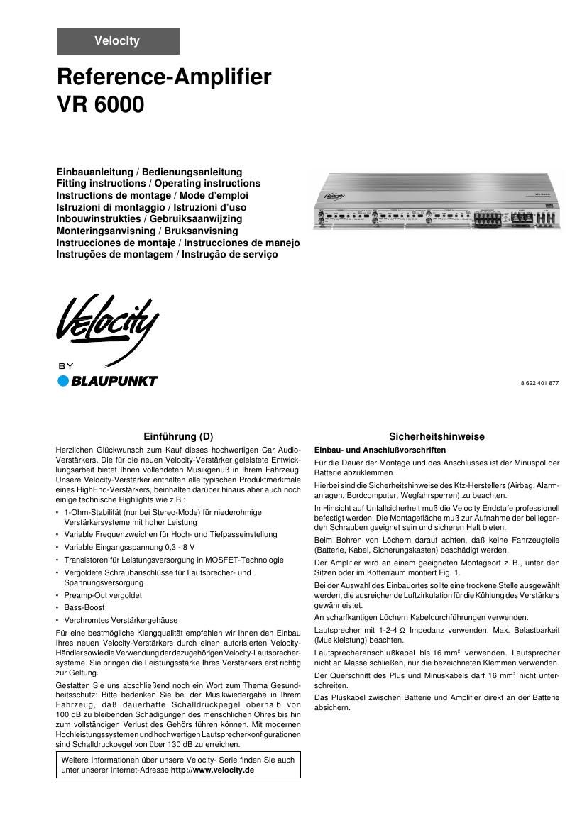
Blaupunkt VR 6000 Owners Manual

This is the 16 pages manual for Blaupunkt VR 6000 Owners Manual.
Read or download the pdf for free. If you want to contribute, please mail your pdfs to info@audioservicemanuals.com.

Page: 1 / 16
left right
Blaupunkt VR 6000 Owners Manual

Extracted text from Blaupunkt VR 6000 Owners Manual (Ocr-read)


Page 1

2 Velocity Reference Amplifier VR 6000 Der Amplifier eignet sich zum Anschluß an Autoradios mit Cinch- Anschluß. Für den Anschluß an Autoradios mit ISO-Anschluß Blaupunkt ISO- Cinch Adapter verwenden. Einsatzmöglichkeiten und Lautsprecheranschluß: VR 6000 Max Power 4x110 + 2x220 Watt Fig. 5 4 Ohm Max Power 4x160 + 2x300 Watt Fig. 5 2 Ohm Max Power 4x180 + 2x360 Watt Fig. 5 1 Ohm RMS Power 4x55 + 2x110 Watt Fig. 5 4 Ohm (THD @ 0,05 %) RMS Power 4x80 + 2x150 Watt Fig. 5 2 Ohm (THD @ 0,1 %) RMS Power 4x90 + 2x180 Watt Fig. 5 1 Ohm (THD @ 0,2 %) Frequenzgang 10 Hz - 60 kHz - 3 dB Signal-Rausch- > 95 dB abstand Eingangs- 0,3 - 8 V empfindlichkeit Hochpassfilter 40 - 250 Hz (High Pass) Tiefpassfilter 40 - 120 Hz (Low Pass) (18 dB / Oct.) Abmessungen 232,6 x 59,5 x 620 BxHxT (mm) Tri - Mode Sie können 2 Lautsprecher(4-„¦) betreiben und gleichzeitig einen dritten Lautsprecher (4-„¦) im Mono - Betrieb (Brückenbetrieb) dazuschalten. Plus-/Minus-Anschluß Wir empfehlen einen Mindestquerschnitt von 16 mm 2. Handelsübliche Pluskabel zur Batterie verlegen und über Sicherungshalter anschließen. Den Sicherungshalter in der Nähe der Batterie anschließen. An scharfkantigen Löchern Kabeldurchführungen verwenden. Handelsübliche Minuskabel an einen störfreien Massepunkt (Karosserieschraube, Karosserieblech) sicher anschrauben (nicht am Minuspol der Batterie). Kontaktfläche des Massepunktes metallisch blank kratzen und mit Graphitfett einfetten. Anschlußbeispiele Anschluß der Spannungsversorgung ........................................... Fig. 2 Anschluß an Autoradios mit Cinch-Ausgang ............................... Fig. 3 Anschluß an Autoradios mit Lautsprecher-Ausgang .................... Fig. 4 Lautsprecheranschlüsse .............................................................. Fig. 5 Beim Anschluß über die Cinch- oder Lautsprecherbuchsen des Autora- dios muß die Schaltleitung angeschlossen werden. +12V Regler GAIN Mit Hilfe des Gain Reglers kann die Eingangsempfindlichkeit der Velocity Endstufe an die Ausgangsspannung Ihres Autoradio- Vorverstärkeraus- ganges angepaßt werden. Der Einstellbereich reicht von 0,3 V bis 8 V. Bei Anschluß eines Autoradios anderer Hersteller ist die Eingangs- empfindlichkeit entsprechend den Herstellerangaben anzupassen. Bitte bemerken Sie das der Gain Adjust Regler keine Lautstärkeein-stellung ist! Preamp - INPUT Vorverstärker- Eingang für rechten (right) und linken (left) Kanal. Zu diesem Anschluß verwenden Sie hochwertige Velocity-Chinch / RCA- Kabel. LP / HP / FULL - Schalter Selektieren Sie vor der Montage den Crossover Schalter der Endstufe um den Tiefpassfilter (LP), den Hochpassfilter (HP) oder Fullrange (Full) einzustellen. Bei der Position Full wird der volle Frequenzgang am Ausgang benutzt. Der Einsatz der integrierten Frequenzweichen ist vor allen sinnvoll bei Mehrwege- Soundsystemen mit separatem Subwoofer. Um einen Subwoofer sinnvoll zu betreiben und somit den besten Klang zu erreichen, ist es notwendig diesen frequenzmäßig abzukoppeln um ihm nur die tiefen (Bässe) Frequenzen zuzuführen. Um dieses zu tun wählen Sie LP und regeln Sie mit Hilfe des Ãœbergangs- frequenzreglers die obere Frequenz zwischen 40 Hz und 120 Hz. Somit wird jeder Subwoofer optimal abgekoppelt. Bei der Selektion HP kann mit dem zugehörigen Ãœbergangsfrequenz- regler die untere Grenzfrequenz zwischen 40 Hz und 250 Hz variiert werden. Zur genauen akustischen Abstimmung der Frequenzweiche empfehlen wir Ihnen die Beratung durch einen Velocity Fachhändler. Die technischen Daten der eingesetzten Lautsprecher müssen bei der Abstimmung der Frequenzweiche unbedingt berücksichtigt werden. Ãœbergangsfrequenzregler (LP + HP) Ist über den Crossover Schalter die Frequenzweiche aktiviert (Lowpass oder Highpass), kann mit dem entsprechenden Regler die Ãœbergangs- frequenz des jeweiligen Filters zwischen 40 Hz und 250 Hz stufenlos eingestellt werden. Bei Fullrange- Betrieb ist dieser Regler ohne Funk- tion. Integrierte Sicherungen (FUSE) Die im Amplifier integrierten Sicherungen (Fuse) schützen die Endstufe und das gesamte elektrische System im Fehlerfall. Bei dem Einsatz einer Ersatzsicherung bitte niemals Sicherungen überbrücken oder gegen Typen mit höherem Strom auswechseln. Betriebsanzeige (POWER / PROTECT) Grünes Licht: Endstufe an, regulärer Betriebszustand Rotes Licht: Endstufe ist elektronisch abgeschaltet da Fehlerfall vorliegt. Änderungen vorbehalten! 8 622 401 877

Page 2

3Velocity ReferenceAmplifier VR 6000 The amplifier is suitable for connecting to car radios with cinch connector. Use the Blaupunkt ISO-Cinch Adapter for connecting to car radios with ISO connector. Possibilities for use and switching: VR 6000 Max Power 4x110 + 2x220 W Fig. 5 4 Ohm Max Power 4x160 + 2x300 W Fig. 5 2 Ohm Max Power 4x180 + 2x360 W Fig. 5 1 Ohm RMS Power 4x55 + 2x110 W Fig. 5 4 Ohm (THD @ 0.05 %) RMS Power 4x80 + 2x150 W Fig. 5 2 Ohm (THD @ 0.1 %) RMS Power 4x90 + 2x180 W Fig. 5 1 Ohm (THD @ 0.2 %) Freq. response 10 Hz - 60 kHz - 3 dB Signal-to-Noise > 95 dB Ratio Input Level 0,3 - 8 V High Pass 40 - 250 Hz Low Pass 40 - 120 Hz (18 dB / Oct.) Dimensions 232.6 x 59.5 x 620 WxHxD (mm) Tri-Mode Allows you to drive two loudspeakers (4-„¦) and to connect a third speaker (4-„¦) in mono operation (bridged mode). Positive/negative connections We recommend a minimum cross-section of 16 mm 2. Lay commercially available positive cable to the battery and connect using fuse holder. The fuse holder should be connected close to the battery. Use cable bushings at sharp-edged holes. Screw the commercially available negative cable firmly to an interference-free earthing-point (car body bolt, car body sheet, but not to the negative battery pole). Scrape the contact surface of the earthing point until it is blank metal and coat with graphite grease. Connection examples: Connection of power supply ........................................................ Fig. 2 Connection of car radio with cinch output ................................... Fig. 3 Connection of car radio with loudspeaker output ........................ Fig. 4 Loudspeaker connections ........................................................... Fig. 5 When connecting via the cinch or loudspeaker sockets of the car radio the switch cable must be connected. +12V Controller (GAIN) Using the Gain Controller you can adjust the input sensitivity of the Velocity Power Amplifier to the output voltage of your car radio pre- amplifier output. The adjusting range is from 0.3 V to 8 V. When connecting a car radio from other manufacturers the input sensitivity should be adapted in accordance with the specifications of the manufacturer. Introduction (GB) Congratulations on purchasing this high-quality Car Audio Amplifier. The development work invested in the new Velocity Amplifier offers you complete music enjoyment in your car. Our Velocity Amplifiers are fitted with all typical product features expected from a high-end amplifier, but also contain a number of technical highlights as well, such as: - 1 ohm stability (only in stereo mode) for low-ohm amplifier systems with high performance - Variable frequency dividers for high and low pass setting - Variable input voltage 0.3 - 8 V - Transistors for power supply using MOSPET technology - Gold-plated screw connectors for loudspeaker and power supply - Preamp-Out gold-plated - Bass-Boost - Chrome-plated amplifier housing To achieve the best possible sound quality from your new Velocity Amplifier we recommend that it is installed by an authorised Velocity dealer and that the matching Velocity Loudspeaker system is used. This is the way to obtain the full enjoyment of the performance of your amplifier. Let us finally mention the aspect of health safety. Please remember when listening to music in your car that constant sound-pressure levels of more than 100 dB can cause permanent damage to the human ear right up to complete loss of hearing. Sound-pressure levels of more than 130 dB can be achieved with modern high-performance systems and high- quality loudspeaker configurations. You can also obtain further information on our Velocity Series at our Internet address http://www.velocity.de Safety instructions Rules to be observed in fitting and connection Disconnect the negative pole of the car battery for the duration of the installation and connection works. The safety instructions of the car manufacturer (airbag, alarm systems, on-board computers, engine immobilizers) must be observed. With regard to accident prevention the Velocity power amplifier must be affixed in a professional manner. The mounting surface must be suitable for accepting the enclosed screws and must offer secure installation. When drilling holes please ensure that no car components are damaged (battery, cables, fuse box). The amplifier should be installed at a suitable location, i.e. under the seats or in the boot, Fig. 1. A dry position should be selected for the installation location that guarantees sufficient air circulation for the cooling of the amplifier. Use cable bushings at sharp-edged holes. Use loudspeakers with 1-2-4 ohm impedance. Pay attention to the max. loading (music output). Use 16 mm 2 loudspeaker connection cables. Do not connect the loudspeakers to earth, use only the designated terminals. The cross-section of the positive and negative cable may not be less than 16 mm 2. Fit a fuse holder to the positive cable between the battery and the amplifier directly at the battery. 8 622 401 877