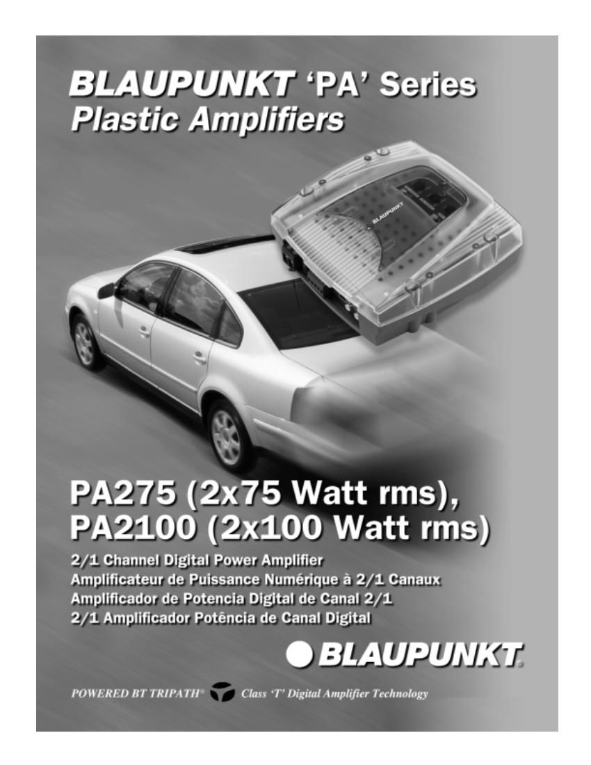
Blaupunkt PA 2100 Owners Manual

This is the 15 pages manual for Blaupunkt PA 2100 Owners Manual.
Read or download the pdf for free. If you want to contribute, please mail your pdfs to info@audioservicemanuals.com.

Page: 1 / 15
left right
Blaupunkt PA 2100 Owners Manual

Extracted text from Blaupunkt PA 2100 Owners Manual (Ocr-read)


Page 1

Below is a basic trouble-shooting guide to assist in seeking out and correcting a problem that may occur in the installation process. Although lengthy, this chart cannot address every single problem poss ble but mainly the ones most common. PARAMETER/FEATURE PA275PA2100 Channels 2/1 2/1 Size ( W x H x D) 7.9 x7.5x2.6 inches (200x190x67mm 7.9 x7.5x2.6 inches (200x190x67mm) Weight (with housing)4.6 lbs (2.1 kg)4.6 lbs (2.1 kg) Crimping style speaker terminals? YESYES Maximum terminal wire size 14 ga.14 ga. Subsonic filter YES (10 Hz)YES (10 Hz) Separate front/rear or left/right gains? NONO Fuse Type ATC spade -30AATC spade -40A Speaker short, short to +12V, and short to ground protection? YES YES High, low, and reverse voltage protection? YESYES Power output transistors MOSFETMOSFET Switching power supply transistors MOSFETMOSFET Minimum speaker impedance (non-bridged) 2 ohms 2 ohms (bridged)4 ohms 4 ohms PERFORMANCE DATA Rated power output @ 0.1% THD, 13.8V 2 channels into 4 ohms / 2 ohms 2 x 75 W / 2 x 100 W 2 x 100 W / 2 x 150 W 1 channel into 4 ohms 1 x 200 W1 x 300 W Total Harmonic Distortion @ rated full output 0.03% THD0.03% THD Rated Signal/Noise ratio (averaged value) Measured @ 1 watt / 1 kHz dBA82 82 Measured @ full rated power (0.1% THD) dBA >100>100 Damping factor >100>100 Frequency response (full-range mode) 20 - 50,000 Hz20 - 50,000 Hz High-pass crossover frequency limits 50 H z - 250 Hz (variable), 12dB/oct 50 H z - 250 Hz (variable), 12dB/oct Low-pass crossover frequency limits 50 H z - 250 Hz (variable), 12dB/oct 50 H z - 250 Hz (variable), 12dB/oct Input impedance 10 kohms10 kohms Input signal voltage control range 0.3 - 6.0 vrms0.3 - 6.0 vrms Current Draw @ 13.8 VDC (typical values @ X watts / Efficiency %) @ full rated power, bridged mode (@ 4 ohms) 28 A (65%) 36 A (65%) @ full rated power, unbridged(@ 4 ohms) 16 A (78%) 21 A (78%) @ 33% rated power, unbridged (@ 4 ohms) 6.0 A (60%) 8.0 A (60%) @ 10% rated power, unbridged (@ 4 ohms) 3.0 A (40%)4.0 A (40%) @ idle (@ 4 ohms) 1.2 A 1.5 A Minimum battery voltage to maintain rated power 12.6 VDC12.6 VDC Usable battery voltage 10 - 16 VDC10 - 16 VDC Trigger line voltage range 10 - 16 VDC10 - 16 VDC Trigger line current draw @ 20 mA@ 20 mA Turn on delay time @ 2.0 seconds@ 2.0 seconds Thermal shutoff temperature (average heat-sink temp) @ 85Ëš C (185Ëš F)@ 85Ëš C (185Ëš F) NOTE: DUE TO ONGOING PRODUCT IMPROVEMENTS, DESIGN AND SPECIFICATIONS ARE SUBJECT TO CHANGE WITHOUT ADVANCED NOTICE TO THE CONSUMER OR RETAILER. B LAUPUNKT S PECIFICATIONS - PA275 AND PA2100, 2/1 C HANNEL AMPLIFIER

Page 2

What is an amplifier? . . . . . . . . . . . . . . . . . . . . . . . . . . . . . . . . . . . .\ . . . . . . . . . . . . . . . . . . . . . . . . . . . . . . . . . . . . . . . . . . . . . . .2 Key features . . . . . . . . . . . . . . . . . . . . . . . . . . . . . . . . . . . .\ . . . . . . . . . . . . . . . . . . . . . . . . . . . . . . . . . . . . . . . . . . . . . . . . . . . . . .2 Safety Concerns & installation warnings . . . . . . . . . . . . . . . . . . . . . . . . . . . . . . . . . . . .\ . . . . . . . . . . . . . . . . . . . . . . . . . . . . . . .3 System planning . . . . . . . . . . . . . . . . . . . . . . . . . . . . . . . . . . . .\ . . . . . . . . . . . . . . . . . . . . . . . . . . . . . . . . . . . . . . . . . . . . . . . . . .4 Installation tools . . . . . . . . . . . . . . . . . . . . . . . . . . . . . . . . . . . .\ . . . . . . . . . . . . . . . . . . . . . . . . . . . . . . . . . . . . . . . . . . . . . . . . . . .4 Vehicle wiring . . . . . . . . . . . . . . . . . . . . . . . . . . . . . . . . . . . .\ . . . . . . . . . . . . . . . . . . . . . . . . . . . . . . . . . . . . . . . . . . . . . . . . . . . . .5 Connections & controls . . . . . . . . . . . . . . . . . . . . . . . . . . . . . . . . . . . .\ . . . . . . . . . . . . . . . . . . . . . . . . . . . . . . . . . . . . . . . . . . .6-7 System configurations 1 & 2 . . . . . . . . . . . . . . . . . . . . . . . . . . . . . . . . . . . .\ . . . . . . . . . . . . . . . . . . . . . . . . . . . . . . . . . . . . . . . . .8 System configurations 3 & 4 . . . . . . . . . . . . . . . . . . . . . . . . . . . . . . . . . . . .\ . . . . . . . . . . . . . . . . . . . . . . . . . . . . . . . . . . . . . . . . .9 Troubleshooting chart . . . . . . . . . . . . . . . . . . . . . . . . . . . . . . . . . . . .\ . . . . . . . . . . . . . . . . . . . . . . . . . . . . . . . . . . . . . . . . . . . . .10 Warranty information . . . . . . . . . . . . . . . . . . . . . . . . . . . . . . . . . . . .\ . . . . . . . . . . . . . . . . . . . . . . . . . . . . . . . . . . . . . . . . . . . . . .11 Blaupunkt technical support . . . . . . . . . . . . . . . . . . . . . . . . . . . . . . . . . . . .\ . . . . . . . . . . . . . . . . . . . . . . . . . . . . . . . . . . . . . . . .11 Assembly & Mounting . . . . . . . . . . . . . . . . . . . . . . . . . . . . . . . . . . . .\ . . . . . . . . . . . . . . . . . . . . . . . . . . . . . . . . . . . . .Back Cover T ABLE O F C ONTENTS -“ 1 -“