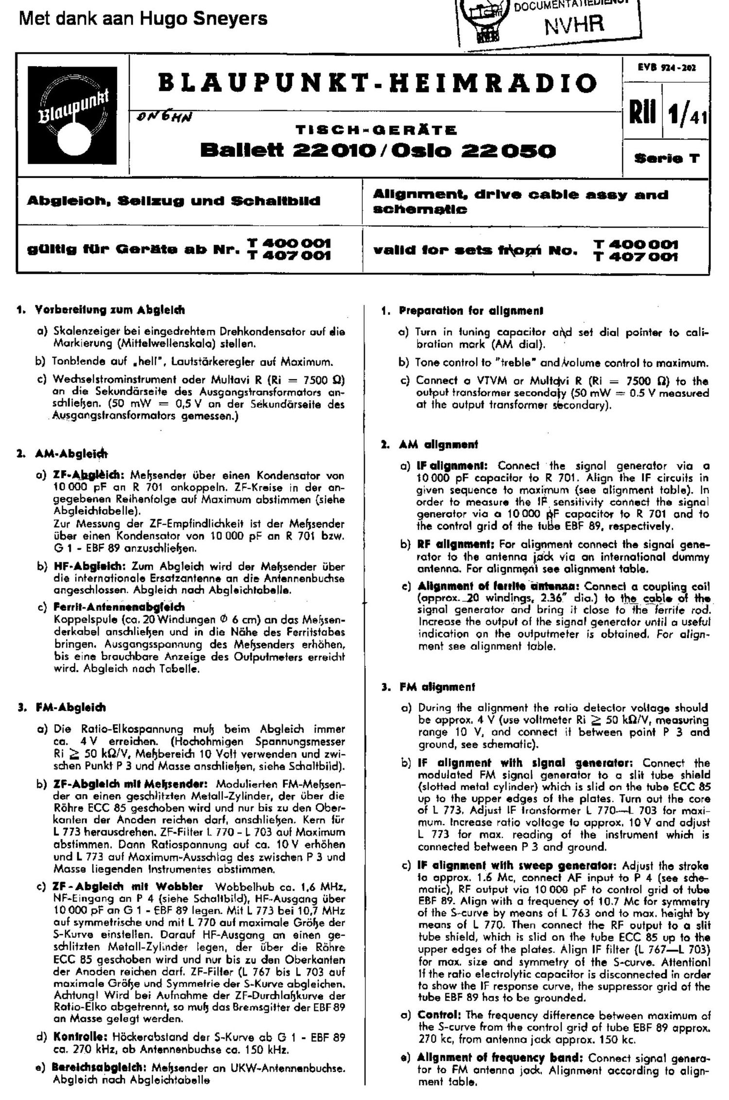
Blaupunkt Oslo 220510 Schematic

This is the 4 pages manual for Blaupunkt Oslo 220510 Schematic.
Read or download the pdf for free. If you want to contribute, please mail your pdfs to info@audioservicemanuals.com.

Page: 1 / 4
left right
Blaupunkt Oslo 220510 Schematic

Extracted text from Blaupunkt Oslo 220510 Schematic (Ocr-read)


Page 1

Met dank aan Hugo Sneyers

BLAUPUNKT-HEIMRADIO

DOCUMENTM lama-w.

NVHR

affirm

Trscr-r-oranlh':

Ballet! 22 010 / Oslo 22 050

Sonic 1'

Abgleioh. Soilzug and Schaliblld

gullig rur- Ger-ma ab up. ; figggg

Alignment. drive cable assay and
schematic

I' 400 00'!

valid to:- sets his" 0- 1- 407001

1. Yorbereitung zurn Abglelsh

a) Skolenzeiger bei eingedrehtem Drehkondensator out die
Markierung (Mittelwellenskola) stellen.

b) Tonblende out .hell', Lautstérrkeregler aut Maximum.

c} Wedrselstrominstrument odor Multavi R {iii = 7500 Q)
an die Sekunclarseite des Ausgangstronsformotors an~
schliehen. (50 mW = 0,5V an der Sekundorseite des
.Ausgongstransformatms gemessen.)

1. AM-Abgleidr

o) IF-Ajmléidl: Mehsender fiber einen Kondensator von
10 000 pF an R 701 onkoppeln. ZF-Kreise in der on-
gegebenen Reihentolge auf Maximum abstimmen (siehe
Abgleichtabelle).

Zur Messung der ZF-Emptindliohkeit ist der Mehsendor
fiber einen Kondensolor von 10 000 pF an R 701 bzw.
G 1 - EBF 89 onxuschlieljen.

b} HF-Abgieidt: Zum Abgleidt wird der Mohsonder iiber
die internalionale Ersatzantonne an die Antennenbucnse

ongeschlossen. Abgleidt noch Alagleichtobella.

c) Ferril-Antennemlbgleldl I
Koppelspule (ca. 20 Windungen (0 6 cm) an dos Mahsen-
derkabel ansdrliehen und in die Né'rhe des Ferritstabes
bringen. Ausgongsspannung des Mefysenders erhohen,
bis eine brouchbare Anzeige des Outputrneters erreicht
wird. Abgleich noch Tabelle.

3. FM-Abgleidr

a) Die Ralio-Elkospannung mulj beim Abgleidw immer
ca. 4 V erreichen. (Hadrohmigen Spannungsmesser
Ri 2 50 RON, Mehbereid'r 10 Volt verwenden und zwi-
schen Punkt P 3 und Mosse onschlieljon, sieha Schaltbild).

b) lF-Abgloldt lltll Mehsender: Modulierten FM-Mebsen-
der an einen geschtitzten Metalllylinder, der fiber die
Rohre ECC 85 geschoben wird und nur bis zu den Ober-
kOnten der Anode-n reichen dart. anschliehen. Kern tiir
L 1'73 herausdrehen. ZF-Filter L 770 - L 703 out Maximum
abstimmen. Donn Ratiosponnung out ca. 10V erhohen
und L 7?3 out Moximum-Aussdilog des zwisdren P 3 und
Masse liegenden lnstrumentes abslimmen.

c) ZF-Abgleid'r mil Wobbler Wobbelhub ca. 1.6 MHz.
NF-Eingang on P 4 (siehe Schallbild), HF~Ausgang fiber
10000 p? on G 1 - EBF 89 Iegen. Mil L 773 bei 10.7 MHz
out symmetrische und mit L 770 out maximole Grohe der
S-Kurvo einslelten. Darauf HF-Ausgang an einen ge-
sdtlitzten Metall-Zylinder legen. der ij'ber die Rohre
ECC 85 gesdsoben wird und nur bis zu den Oberkanten
der Anoden reichen dart. ZF-Filler (L 76'! bis L 703 out
moximale Grohe and Symmetrie der S-Kurve abgleicl'lon.
Act-flung! Wird bei Autnahme der ZF-Durchlahlrurve der
Rotio-Elko obgetrennt. so mulj dos Bremsgitter der EBF 89
on Masse gelegt werden.

d) lionlrolie: Hockorabstand der S-Kurvo ob G 1 - EBF 89
ca. 270 kHz. ob Antennonbuchse ca. 150 kHz.

e) Bould'llabgletcll: Melsender on UKW~Antennenbuchse.
Abgloich nocl'i Abgloichtobello

1. Preparation tor ollgnrnenl

0) Turn in tuning capacitor and set dial pointer to coli-
bratian mark (AM dial}.

b) Tone control to "treble and holume control to maximum.
c} Connect a VTVM or Multdvi R (Ri = 7500 o} to the

output transformer secondaty {50 «M! = 0.5 V measured
at the output transformer secondary].

2. AM alignment

a) IF alignment: Connect the signal generator via a
10000 pF capacitor to R 701. Align the IF circuits in
given sequence to maximum (see alignment table). In
order to measure the IF sensitivity connect the signal
generator via CI 10000 F capacitor to R 701 and to
the control grid at the tu e EBF 89. respectively.

b] IF alignment: For alignment connect the signal gene-
rate» to the antenna ind; via an international dummy
antenna. For alignment see alignment table.

:1 Alignment of lerrlie'irntem: Connect a coupling coil
(approx. 30 windings. 2.36," dia.) to it); cgblo ot the
signal generator and bring it close to the ferrite rod.
Increase the output of the signal generatOr until a useful
indication on the outputmeter is obtained. For align-
ment see alignment table.

3. FM alignment

0) During the alignment the ratio detector voltage should
be approx. 4 V (use voltmeter Ri 2 50 kn/v. measuring
range 10 V. and connect it between point P 3 and
ground, see schematic).

b) IF alignment with signal generator: Connect the
modulated FM signal generator to a slit tube shield
(slotted metal cylinder) which is slid on the tube ECC 85
up to the upper edges at the plates. Turn out the core
of L 7'23. Adjust lF transformer L 770---L 703 for maxi-
mum. Increase ratio voltage to approx. 10V and adjust
L 773 tor max. reading at the instrument which is
connected between P 3 and ground.

c) IF alignment with sweep generator: Adjust the stroke
to approx. 1.6 Mc, connect AF input to P 4 (see sche-
matic), RF output via 10 000 pF to control grid at tube
EBF 89. Align with a trequency at 10.7 Mr: tor symmetry
ot the S+curve by means of L 763 and to max. height by
means at L 770. Then connect the RF output to a slit
tube shield, which is slid on the tube ECC 35 up to the
upper edges of the plates. Align IF filter {L ?67-L 703)
for max. size and symmetry of the S-cuwe. Attention]
It the ratio electrolytic capacitor is disconnected in order

to show the IF response curve. the suppressor grid at the
tube EBF 89 has to be grounded.

a) Control: The frequency ditterence between maximum of
the S-curve from the control grid of tube EBF 89 approx.
270 kc, from antenna jack approx. 150 kc.

e) Allgnment at frequency band: Connect signal genero-

tor to PM antenna jock. Alignment according to align-
ment table.