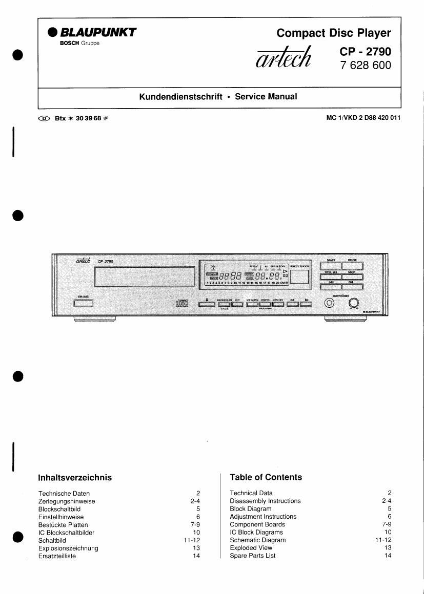
This is the 14 pages manual for Blaupunkt CP 2790 Service Manual.
Read or download the pdf for free.
If you want to contribute, please mail your pdfs to info@audioservicemanuals.com.
Dieses Gerat entspricht den Sicherheitsbestimmungen nach VDE
0860 und somit den internationalen Sicherheitsvorschriften lEC 65
bzw. CEE 1, die bei jeder Reparatur zu beachten sind.
Alle Bauteile, die mit einem solchen Symbol A gekennzeichnet sind,
miissen durch Originalteile ersetzt werden.
Hinweis: Der CP-2790 ist mlt einem Halbleiter-Laser ausgestat-
tet, der unsichtbares Licht ausstrahlt. Vermeiden Sieiede Beriih-
rung mit dem Laser und schauen Sie nlemals bei eingeschalte-
tem Gerit in die optische Linse.
Technische Daten
This unit meets the VDE 0860 safety regulations and consequently
also the International Safety Specification lEC 65 or CEE 1, and have
to be observed when repairing the set.
All components marked by A have to be replaced by original parts.
Note: The CP-2790 is equipped with a semiconductor laser.
Therefore, touching with the laser should be avoided and do
never look directly Into the optical lens when the unit is turned
on.
Technical Data
Bezeichnung Wen / Value Designation
NetzanschluB 220/240V, 50/60 Hz Mains Voltage
Leistungsaufnahme 12 Watt Power Consumption
Frequenzbereich 4 Hz - 20 kHz : 0.5 dB Frequency Response
Dynamikumfang 96 dB Dynamic Range
Gerauschspannungsabstand 100 dB Weighted S/N Ratio
Kanaltrennung bei 1 kHz 90 dB Channel Separation at 1 kHz
Klirrfaktor bei 1 kHz 0,03 % Distortion at 1 kHz
Abtasttrequenz 882 kHz Oversampling
Quantisierung 16 Bit Quantization
Ausgangsspannung / Impedanz Output Voltage/ Impedance
AUSGANG 2 V I 5 kn "AUSGANG "
KOPFHORER 12 V / 32 (2 "KOPFHORER"
Abmessungen Breite: 443 mm Dimensions Width
Héhe: 95 mm Height
Tiefe: 285 mm Depth
Masse 4,0 kg Weight
Zerlegungshinweise ' Disassembly Instructions
1. Abnehmen des Gehiiuseobertells
- Je zwei Schrauben seitlich und eine Schraube oben in der
Riickwand herausdrehen.
2. Abnehmen der Schubladenblende
- Das Zahnrad D Fig. 3 in Pfeilrichtung drehen und die
Schublade ca. 5 cm herausfahren.
- Die Blende an der Unterkante etwas abziehen und nach
oben schieben,
Fig. 1
Schublade
Disc tray
3. Ausbauen der Frontblende
- Die Pkt, 1 und 2 durchfiihren.
- Die Kabel vom Netzschalter abloten.
~ Dia Stecker JP 8 und JP 9 abziehen.
~ Die 3 Schrauben S herausdrehen.
~ Die Rasthaken A nach innen drilcken.
- Die Frontblende nach vorn abziehen,
- Zum Abnehmen der Metallblende die Rasthaken B und 0
driicken und die Blende vorsichtig abziehen.
1. Removing the upper cabinet part
- Unscrew two screws on each side and one screw at the
top of the rear panel.
- Remove the upper cabinet part.
2. Removing the tray panel
- Turn the toothed wheel D Fig 3, in direction of the arrow
and bring out the disc tray by about 5 cm.
- Slightly detach the tray panel at the lower edge and push it
upwards.
Blende
Tray panel
3. Removing the front panel
Proceed as described in points 1 and 2.
Unsolder the cable from the mains switch.
Pull oft plugs JP 8 and JP 9.
Unscrew the three screws 3.
Press the detent hook A to the inside.
Pull off the front panel to the front.
For detaching the metal panel press detent hooks B and C
and carefully pull the panel oft.
.......