Bang Olufsen Beomaster 900 Service Manual 2

This is the 6 pages manual for Bang Olufsen Beomaster 900 Service Manual 2.
Read or download the pdf for free. If you want to contribute, please mail your pdfs to info@audioservicemanuals.com.

Page: 1 / 6
left right
Bang Olufsen Beomaster 900 Service Manual 2

Extracted text from Bang Olufsen Beomaster 900 Service Manual 2 (Ocr-read)


Page 1

Supplement to Electrical and Radio racing. Dmmim 4. m9

TABLE RADIO tuning LW, MW, SW
and VHF/FM bands. Circuit uses 24
transistors and 10 diodes. Unit is available
for use with separate speaker enclosures

(model 900M), with integral speakers
(900K) or incorporated in radiogram
model 900RG.

Mains. 110, 130, 220, 240V AC SOc/s.

Consumption. low at IOOmW output,
65W at maximum output.

Transistors. TRl BFllS; TRZ RH 15;
TR]AF116/AF126;TR4 AFllG/AFllo;
TR4B 0C7l; TR5 2N2654/AF121; TR6
AC15l;TR7 ACISI; TR8 AClSl; TR9
AClSl; TRIO ACISS; TRll AC153;
TRIZAC132;TRlSAC127;TR14ACl32;

TRIS ACI27; TR16 ACISé; TRI7
ACISl; TRIS ZNSSS; TR19 BC154;
TRZO BC154; TRZI AD139; TRZZ

AD139; TR23 AD139; TR24 ADl39.

Diodes. D1 OA90; D2 ZEAlOl; D3
OA7D; D4 0A79; D5 0A79; D6 0A90;
D7 OA79; D8 AAII9; D9 AA119;
D10 IN757A.

Wavebands. LW 2040-357m (I47-
350kc/s); MW 578-188m (520-1600kc/s);
sw 50.4-48.4m (5.95-6.2mc/s); VHF/FM
87.5«l08mc/s.

IFS. AM 468kc/s, FM 10.7mc/s.

Picture shows stereo tuner/amplifier
Beomaster 900M. This unit is incorporated
in the Beamaster 900K radio which has
integral speaker enclosures with grooved
baffles at the ends, and in the radiogrim
Beomaster YOORG. All models will accept
the decoder which is available separately.
Cabinets have teak or rosewood finish

Aerials. MW, LW internal ferrite rod.

Pilot lamps. LPl stereo indicator lamp
19V 0.097A; LPZ, LP3 dial lamps 6.3V
0.3A.

Outlets. 5-contact DIN socket for
mono and stereo recorders. Diode
output IOOmV at Ike/s; playback 4SOmV
at lkc/s. DIN socket for two side speakers
and one additional speaker on left channel.

Fuses. FSl lA fuse link; F82, F53
ZSOmA.
Output. 6W per channel continuous,

8W per channel peak.

Speakers. Model 900K, 3.20hm im<
pedance ellipitical.
Dimensions. 900K 29f X 53 X 9%.;

900M 155 X 5% X 9am.

Manufacturer. Bang & Olufsen, Den-
mark.

Service Department. Eastbrook Road,
Gloucester. Tel: Gloucester 21591.

. SERVICE NOTES
In model 900K, cabinet forms pressure
chamber for speakers so that if chassis is
removed from cabinet power fed to
speakers must be limited to avoid damage
to speaker cones.

BEOMASTER
900K, 900M,
9OORG

STEREO TUNER/
AMP! iFlFR

Fer Sorvloa Manual.
MAURITRON SERVICES
8 Cherry Tran Road, Chlnnor
Oxfordshlro, OX9 4QY.
Tel (01644) 351694
Fax (01844) 352554
email:- maunimnodiai.pipex.com

ALIGNMENT

Equipment requires. AM/FM signal
generator; sweep generator; oscilloscope;
AF output meter; dummy aerial; lDOKpF
capacitor; polystyrene cement; trimming
tools.

General. Maintain output of about
SOmW with volume control fully advanced
to prevent AGC action masking alignment
peaks. ,

AM IF. Select MW and fully mesh
tuning capacitor. Apply 468kc/s signal
with about ZOkc/s frequency swing from
sweep generator through lOOKpF capa-
citor to base of TR]. Detune coils L2.
Ll and L18. Connect scope to AM
detector stage and adjust in turn cores
L43/44, L38. L37, L32, L31 for symmetry
and maximum response.

Band Width of Skc/s illSkc/s at 6:18
should be obtained. Sensitivity at TR}
base for SOmW output, 1microvolt; at
TR4 base 7microvolts; at TRS base
230microvolts.

Transfer signal to aerial socket and
adjust core of L2 for minimum response.
Fully open tuning gang and adjust core of
L1 for minimum response. Inject signal

For Sirvlco Menu-II
MAURITRON SERVICE!
3 Cherry Tree Road, Chlnnv
Oxlerdohln, 0X9 40Y.
Tel (01544) 351694
Fax (01844) 352554
email? mauriirnnOdialplpexcci

rs: 903 902 905907 m 105m .-92 97- -as i E:
a m-
D I I ll R219 cm H} I am L37 RZOI L31 I N
E mo CZZl L44 am us not; L32 7 605 E]
904 R222 cm 07 m RZlB L39 L35 62' W
c209 no I I I
- 35 czu Lu 953; S: to; m
7 cm L42 L36
W azze cm U5 ' "

- @ 2227 c229 us m 6 u

on IZS m: c2): {:1 spa -
- . @ IE 8 mono -6l5 an
.20 an
m In mzz }
in 124 72' I @ Ei
«:4 55' 3
"2- 103' i
127- IOZ- .
"-5 tstéggtggiet'twewwmsea a
o o o o o o o o o o o o o o o o o o o o o o o of i
O 0 0 0 0 0 D 0 0 0 O 3 D 0 O O D O O O O O O 0! r
. i
la II no no oooooo'oooc f
72 o o a o o o o o a o o 0 oh
I 709 a .
-0 E 0 o 0 O 0 O O o O 0 0 O 0 I
-554§
.
I 729- g -727 l
717 m- -m L! -551 -§5i'

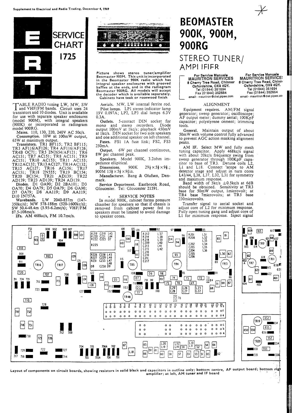
Layout of components on circuit boards, showing resistors in solid black and capacitors in outline only: bottom centre,

amplifier; at left, AM tuner and IF board

Ir i

AF output board; bottom rig

Page 2

er 4. l)"

Picture shows stereo tuner/amplifier
Beomaster 900M. This unit is incorporated
in the Beomaster 900K radio which has
integral speaker enclosures with grooved
baffles at the ends, and in the radiogram
Been-taster YOORG. All models will accept
the decoder which is available separately.
Cabinets have teak or rosewood finish

Aerials. MW, LW internal ferrite rod.

Pilot lamps. LPI stereo indicator lamp
19V 0.097A; LPZ, LP] dial lamps 6.3V
0.3A.

Outlets. S-contact DIN socket for
mono and stereo recorders. Diode
output 100mV at lkc/s; playback 450mV
at Ike/s. DIN socket for two side speakers
and one additional speaker on left channel.

Fuses. FSl lA fuse link; F52, F53
ZSOmA.
Output. 6W per channel continuous,

8W per channel peak.

Speakers. Model 900K, 3.20hm im-
pedance ellipitical.
Dimensions. 900K 29* X 5% x 9%.;

900M 15; x55; x9gin.

Manufacturer. Bang & Olufsen, Den-
mark.

Service Department. Eastbrook Road,
Gloucester. Tel: Gloucester 21591.

. SERVICE NOTES
In model 900K, cabinet forms pressure
chamber for speakers so that if chassis is
removed from cabinet power fed to
speakers must be limited to avoid damage
to speaker cones.

BEOMASTER
900K, 900M,
900RG

STEREO TUNER/
AMPLIFIER

Additional copies of this chart 13.6d.

including postage. Payment with

order please to ER T. Dorset House,
Stamford Street, Landon, SE1 .

ALIGNMENT

Equipment requires. AM/FM signal
generator; sweep generator; oscilloscope;
AF output meter; dummy aerial; 100KpF
capacitor; polystyrene cement; trimming
tools.

General. Maintain output of about
SOmW with volume control fully advanced
to prevent AGC action masking alignment
peaks. -

AM 1F. Select MW and fully mesh
tuning capacitor. Apply 468kc/s signal
with about 20kc/s frequency swing from
sweep generator through lOOKpF capa-
citor to base of TR}. Detune coils L2,
L1 and L18. Connect scope to AM
detector stage and adjust in turn cores
L43/44, L38, L37. L32, L31 for symmetry
and maximum response.

Band width of Skc/s $0.5kc/s at GdB
should be obtained. Sensitivity at TR3
base for SOmW output, Imicrovolt; at
TR4 base 7microvolts; at TR5 base
230microvolts.

Transfer signal to aerial socket and
adjust core of L2 for minimum response.
Fully open timing gang and adjust core of
LI for minimum response. Inject signal

to. ferrite aerial and adjust LIB for
minimum response.

AM RF. Select LW and set tuning
cursor to ISSkc/s. Apply lSSkc/s signal
With 30 per cent AM at 400 c/s to aerial
socket. Adjust core of L28 for maximum
output selecting peak nearer chassis. Set
receiverand signal generator to ZSSkc/s
and adjust C74 for maximum output.

Select MW, tune receiver and signal
generator to S75kc/s and adjust L26 for
maximum output Set receiver and signal
generator to 1495kc/s and adjust C73 for
maxtmum output.

Select SW and tune receiver and signal
generator to 5.95mc/s. Adjust 1.22 for
maximum output. Set receiver and signal
generator to 7.45mc/s and adjust C72
for maximum output.

Select LW and tune receiver to 155kc/s.
Inject 155kc/s signal to ferrite aerial and
adjust position of L8 on aerial to get
maximum response. Tune receiver and
signal generator to ZSSkc/s and adjust
C63 for maximum output.

Switch receiver to MW and tune to
S75kc/s. Inject S75kc/s signal and adjust
position of L17 on ferrite rod to get
maximum output. Tune receiver and
signal generator to 149Skc/s and adjust
C66 for maximum.

Select LW and tune receiver to lSSkc/s.
Inject l55kc/s signal to aerial socket
through dummy aerial and tune L9/l0
for maximum output. Tune receiver and
signal generator to 285kc/s and trim C25
for maximum output.

Select MW and tune set and signal
generator to 575kC/s. Adjust core of
L13/l4 for maximum. Tune set and
generator to l495kc/s and trim C57 for
maximum.

Select SW and tune receiver and
generator to 5.95mc/s and adjust 1.19/20
for maximum. Tune receiver and generator
to 7.45mc/s and trim C60 for maximum.

FM IF. Select FM band and position

continued overleaf

to us .20

19 C2I9 L4!

'20 CZZI L44 I

22 C223 07 Kg}:

.25 cm
can
CZIS

|I7

26 CZ?! L45

27 {229 L46

3! 625} L47
48

L
C230 D9


Ea

J

6H-

"?-I03 605
I02- I
$5333338393§9§§§g§9§§ $223418 I
ooooooooooooooooooooooooi '
OOOOOOOOOOOOOOD600000000! m g
. mf-éy
oo oo oooooooooc
oo no 0000000005 IE [-655
oo 00 can can one: 636- [-555 Al? 42
' . 4I
E i-sn ITRZSI-
-554; 4I7 26
-65| IE] , 424--
-55x -55. .EIE}
427

t; resistors in solid black and capacitors in outline only: bottom centre,
amplifier; at left, AM tuner and IF board

AF output board; bottom rigre FM RF and tuner board; top right, AF
l

For Service Manuals Contact
MAURI'I'RON TECHNICAL SERVICES
8 Cherry Tree Rd, Chinnor
Oxon OX9 4QY

Tat-01844351694

Fax:- 01 WSW

Email:- enqiiiriestomauritmnmut